Section 2.3- piston, rings, connecting rod, Oversize piston & rings, Prior to removai – Generac Power Systems NP-40G User Manual
Page 44: Removai, Piston
Attention! The text in this document has been recognized automatically. To view the original document, you can use the "Original mode".
_________ Section 2.3- PISTON, RINGS, CONNECTING ROD
Oversize Piston & Rings
Worn or scored cylinders may be rebored to 0.010
(OJZSmm) or 0.020 (0.50mm) oversize. Pistons and pis
ton rings of matching oversize are
available
to fit the
rebored cylinder.
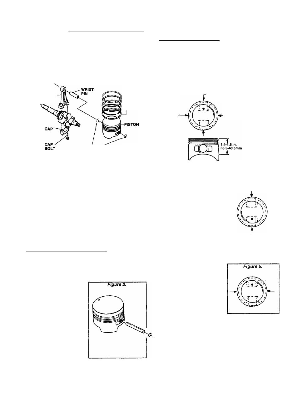
Figure 1. Piston, Rings and Connecting Rod
CONNECTING -
ROD
-RINGS
SNAP"
RING
Prior to Removai
Before removing pistons, rings and connecting rod,
clean all carbon from the cylinder bore. Carbon buildup
In the cylinder bore can cause ring breakage during
piston removal.
Removai
Remove the connecting rod CAP BOLTS and the con
necting rod CAP. Then, push the piston and connecting
rod out through top of cylinder.
Piston
REMOVE FROM CONNECTING ROD;
NOTE: An oil hole In the wrist pin area of the piston
helps distribute oil to assist In cooling. The oil hole
also provides an assist In removing the wrist pin
snap ring.
To remove the piston from
the connecting rod, proceed
as follows:
1. Move the snap ring around
until its protruding end is
aligned with the notched out
oil hole. Use needle nose pli
ers to turn the snap ring and
puil it toward you.
2. With one snap ring re
moved, slide the wrist pin
out of the piston boss. This
will separate the piston from
the connecting rod.
CHECK FOR PISTON WEAR:
The piston is slightly elliptical. It’s smaller diam
eter is in line with the wrist pin boss. It’s larger
diameter is 90° from the wrist pin boss.
NOTE: An assembly mark Is provided on the piston.
This mark should face the flywheel end of the
crankshaft (3:00 position) during reassembly.
Figure 3. Elliptical Shape of Piston
2.747-2.748 In.
69.789-69.809mm
2.753-2.754 In.
69.939-89-959tnm
To check the piston for wear, proceed as follows:
Figure 4.
1. Minor Diameter:- At a posi
tion directly in line with the
wrist pin hole, measure from
top of piston down to a dis
tance of 1.4-1.6 Inches (35.5-
40.5mm). This is the "minor"
diameter. Measure at this point
to check for wear.
PISTON MINOR DIAMETER (GN190 & GN220)
DESIGN DIAMETER: 2.747-2.748 inch (69.789-
69.809mm)
WEAR LIMIT: 2.745 Inch (69.739mm) Minimum
2. Major Diameter:- At a point
90* from the wrist pin bore,
measure down 1.4-1.6 inches
(35.5-40.5mm). This Is the
"major" diameter. Measure at
this point to check for piston
wear. Replace the piston if wear
limits are exceeded.
3. Check wrist Pin for Looseness:- A rough check for
wear in the wrist pin, wrist pin bore in the piston, or wrist
pin bore In the connecting rod is to check for looseness
or play with the piston assembled to the rod. Looseness
or play Indicates a worn wrist pin, or a worn bore in the
piston or connecting rod.
NOTE: Always apply engine oil to wrist pin and Its
bores during Installation. Wrist pin fit Is very close.
Page 2.3-1