Carburetor disassembly (continued), Cleaning and inspection, Adjustment – Generac Power Systems NP-40G User Manual
Page 60: Carburetor disassembly (contin ued)
Attention! The text in this document has been recognized automatically. To view the original document, you can use the "Original mode".
Carburetor Disassembly (Contin
ued)
3. Remove the IDLE MIXTURE SCREW (Item 22) with
SPRING (Item 21).
4. Remove thie IDLE SPEED SCREW (Item 20) with
SPRING (Item 19).
5. Rotate the THROTTLE VALVE (Item 10) to Its closed
?
osltlon and remove the SCREW (Item 9). Remove the
HROTTLE VALVE.
6. Remove the THROTTLE SHAFT (Item 14), along with
the THROTTLE SHAFT SPRING (Item 13) and the THROT
TLE SHAFT SEAL (Item 12).
7. Remove the CHOKE VALVE SPRING RETAINER (Item
18). Remove the CHOKE VALVE (Item 17). Remove the
CHOKE SHAFT (Item 15) and the SHAFT SEAL (Item 16).
Section 3.4- CARBURETOR
Cleaning and Inspection
1. Separate all non-metallic parts.
2. Clean metallic parts In a solvent or a commercial
cleaner. Soak the parts no longer than about 30 minutes.
3. Inspect throttle lever and plate. Replace If worn or
damaged.
4. Inspect the Idle mixture screw. Check the point as well
as Its seating surface for damage. Replace the screw, If
damaged.
5. The float bowl must be free of dirt and corrosion. Use
a new float bowl gasket when assembling the bowl.
6. Check the float for damage. Replace, if damaged. The
float setting is fixed and non-adjustable.
7. The carburetor body contains a main Jet tube that Is
pressed In to a fixed depth. Do NOT attempt to remove
this tube. Tube movement will adversely affect carbu
retor metering characteristics.
8. After soaking In solvent, blow out all passages with
compressed air.
Adjustment
The carburetor is equipped only with an idle jet
adjustment. This jet controls the fuel-air mixture
from light to no-load conditions. The carburetor’s
high speed jet is FIXED and NON-ADJUSTABLE.
If the engine is operated at a significantly differ
ent altitude than the factory (900 feet above sea
levei). It may become necessaiy to readjust the idle
jet. The fuel-air mixture must be set LEANER for
high altitudes. If the unit is moved back to a lower
altitude, return the jet to a richer setting.
CAUTIONI
Do NOT adjust the fuel-air mixture excessively
lean. An excessively lean mixture can result in
engine damage.
See Figure 4, next page. Turn the IDLE JET In
ward (clockwise) until it just contacts its seat. DO
NOT FORCE. Then, turn the IDLE JET outward
(counterclockwise) 1-1/8 turns. This initial adjust
ment should allow the engine to be started and
warmed up.
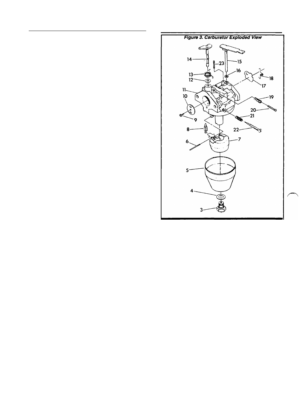
3. Bowl Nut
4. Fiber Washer
5. Float Bowl
6. Float Pin
7. Float
8. Infet Valve
9. Screw
10. Throttle Valve
11. Body
12. Throttle Shaft Seal
13. Throttle Shaft Spring
14. Throttle Shaft
15. Choke Shaft
16. Choke Shaft Seal
17. Choke Valve
18. Choke Valve Spring Retainer
19. Idle Speed Screw Spring
20. Idle Speed Screw
21. Idle Mixture Screw Spring
22. Idle Mixture Screw.
NOTE: Item 20 used
only on Serial No.’s
1354194-1354198 and
1361541-1361600. On
other units. Idle Speed
Screw has been rem
oved.
After the initial adjustment, start the engine and
let it warm up for about five (5) minutes. If the
engine runs rough or if exhaust smoke is black,
proceed as follows:
Page 3.4-2
Revised- 02/07/95