General, Parts list for figure 1, Adjustments – Generac Power Systems NP-40G User Manual
Page 72: The lp gas regulator, Testing the fuel lockoff solenoid
Attention! The text in this document has been recognized automatically. To view the original document, you can use the "Original mode".
Section 4.2- SHUTOFF VALVE & REGULATOR
General
See Figure 1. The fuel shutoff valve (lockoff
solenoid) and the secondary regulator are retained
to a flat mounting bracket which, In turn, mounts to
the generator base cover. The fuel lockoff solenoid
is retained to the mounting bracket by means of a
u-boit The secondary regulator is retained to the
mounting bracket with two
MA“-2Q x
3/4" long
capscrews.
Parts List for Figure 1
ITEM
QTY
DESCRIPTION
1
1
LP Gas Regulator
2
1
Fuel Lockoff Solenoid
3
1
U-Bolt-1.25" wide (5/16‘-18)
4
2
3/4" NPT Street Elbow
5
1
3/4" NPT Close Nipple
6
1
3/8" NPT Street Elbow
7
1
1/2"
X
3/8“ NPT Fitting
8
1
Hose Clamp
9
1
1/2" ID Hose (11.5" long)
10
2
1/4"-20
X
3/4" Capscrew
11
2
1/4" Lockwasher
12
2
5/16" Lockwasher
13
2
5/16"-18Hex Nut
14
1
Regulator Mounting Bracket
15
1
Sleeving (9" long)
Adjustments
There are no adjustments on the fuel lockoff
solenoid or the secondary regulator. This system
is NOT equipped with a load block.
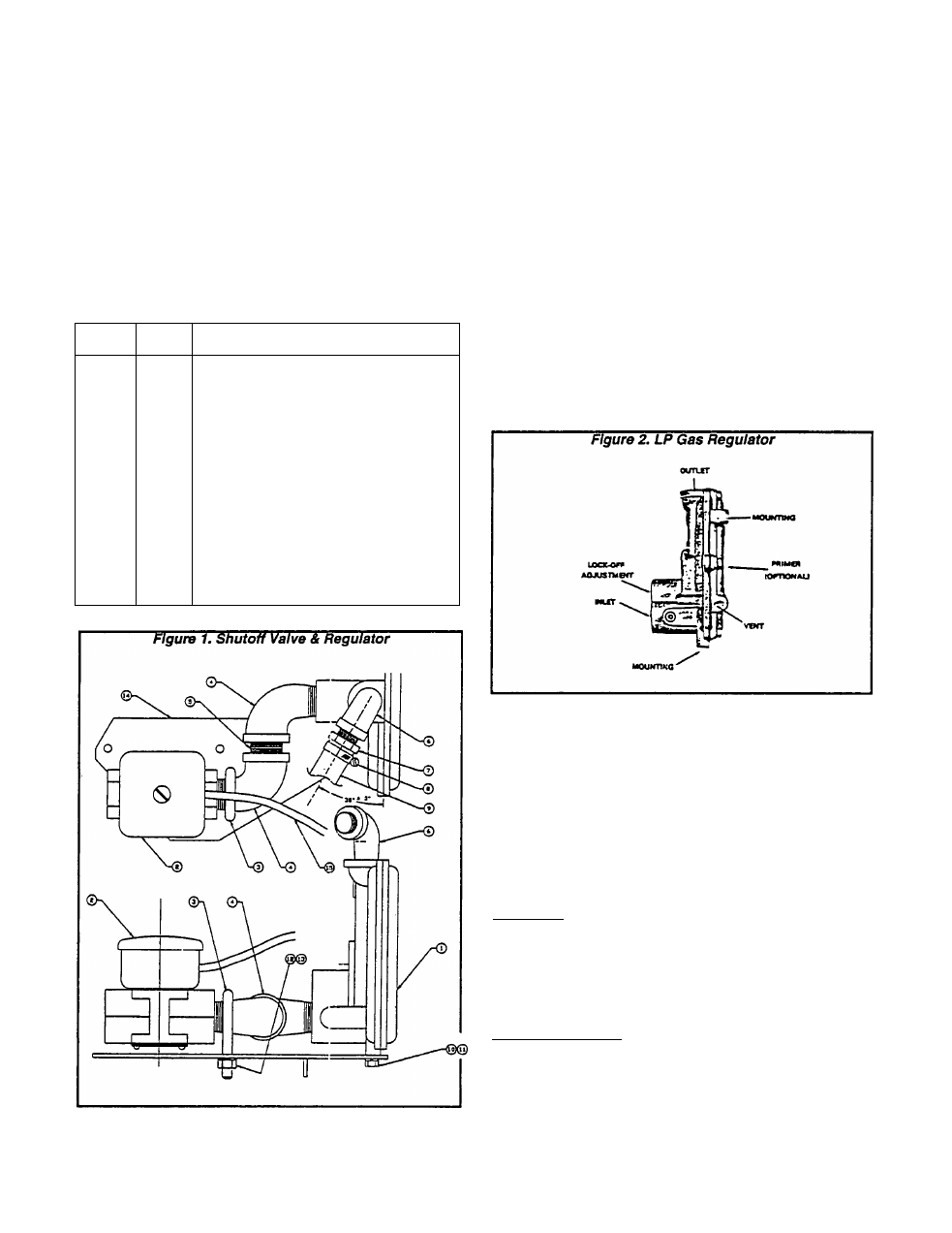
The LP Gas Regulator
The secondary regulator is a GARRETSON®
Model KN. It Is designed for simplicity and simple
operation. The regulator is suitable for use with low
pressure vaporized gaseous fuels where depend
able starting is a requirement. Recommended inlet
pressure to the regulator is 11 inches water col
umn.
The regulator comes with a 3/4 inch NPT fuel inlet
and a 3/8 Inch NPT fuel outlet.
The LOCKOFF ADJUSTMENT SCREW shown in
Figure 2 has been preset at the factory. No addi
tional adjustment Is authorized.
DANGER!
DO NOT ATTEMPT TO ADJUST THE GAS REGU
LATOR. REGULATOR ADJUSTMENTS SHOULD
BE ATTEMPTED ONLY BY QUALIFIED GAS SER
VICE TECHNICIANS WHO HAVE THE KNOWL
EDGE
AND
SPECIALIZED
EQUIPMENT
FOR
SUCH ADJUSTMENTS.
Testing the Fuel Lockoff Solenoid
GENERAL:
The fuel lockoff solenoid Is energized open by 12
volts DC power from the engine controller circuit
board during engine cranking. The solenoid can
also be energized open without cranking by actu
ating the fuel primer switch on the generator panel.
TEST PROCEDURE:
1.
Set a volt-ohm-mllliammeter (VOM) to read
battery voltage (12 VDC).
Page 4.2-1