Genistor, Testing the battery charge circuit – Generac Power Systems NP-40G User Manual
Page 23
Attention! The text in this document has been recognized automatically. To view the original document, you can use the "Original mode".
Section 1.5- COMPONENTS TESTING
4. Connect one VOM test lead to Stator lead AC1,
the other test lead to Stator lead 77. The VOM
should read "Infinity“.
5. Connect one VOM test lead to Stator lead AC1,
the other test lead to Stator lead TIM1. The meter
should read “Infinity”.
6. Connect one test lead to Stator lead PS1, the
other to Stator lead TIM1. “Infinity" should be
Indicated.
7. Connect one test lead to Stator lead PS1, the
other to Stator lead 77. The VOM should read
"Infinity".
8. Connect one VOM test lead to Stator lead TIMI,
the other test lead to Stator lead 77. “Infinity"
should be Indicated.
Genistor
GENERAL:
The “Genistor" or "Triac Module" is the FRE
QUENCY CONVERTER for the generator. For addi
tional Information on the Genistor, refer to
"The
Genistor"
on Pages 1.2-3 and 1.2-4.
SYMPTOMS OF GENISTOR FAILURE:
If the engine shuts down but speed did not ex
ceed 4500 rpm, the following problems may exist:
1. Loss of the "Gate" connection (G1 through G4)
between the CCG circuit board and the Genistor.
2. Although the correct “Gate" signal Is received
from the CCG board, one or more switches are not
gating.
3. The Genistor is not gating properly, I.e., one or
more switches are permanently turned on.
4. Open circuit or loss of connection(s) between
Stator and Genistor (Leads AC1,
a
C2, SLI, SL2,
22).
5.
Open circuit or loss of connection between
Genistor and CCG circuit board (Leads AC1, AC2,
SL1,SL2).
TESTING THE GENISTOR:
Disconnect ail wires from the Genistor before
attempting to test it.
CAUTIONI
DO NOT attempt to test the Genistor until ALL
leads
have
been
disconnected.
The
genistor
MUST be completely disconnected from the cir
cuit If testing is accomplished with any leads
connected, alftest results are Invalid.
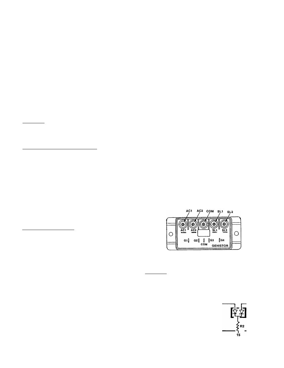
See Figure 4. To test the Genistor, proceed as
follows:
1. Set a VOM to a resistance scale that will allow a
range of about 20-60 ohms to be read. Zero the
meter.
2. Connect one VOM test leads to the "COM" termi
nal and the other test lead to Terminals G1, G2, G3
and G4 one at a time. Read the resistance as the
meter is connected to G1, to G2, to G3, and to G4.
RESISTANCE READING
"COM" to G1 s 20-60 Ohms
"COM" to G2 > 20-60 Ohms
"COM" to G3 o 20-60 Ohms
"COM" to G4 B 20-60 Ohms
3. Set the VOM to its “Rx1” scale and zero the
meter. Then connect the VOM test leads across
the “COM" terminal and the center screw. The
VOM should read “continuity”.
4. Now, connect the VOM test leads across the fol
lowing terminals and screws:
a. Across AC1 screw to AC1 terminal should
read “continuity”.
b. Across AC2 screw to AC2 terminal should
read “continuity”.
c. Across SLI screw to SLI terminal should read
“continuity”.
d. Across SL2 screw to SL2 terminal should read
“continuity”.
5. Set the VOM to its “Rxl 0,000” or “RxlK” scale
and zero the meter. Then, connect the VOM test
leads across each of the screws. There should be
no continuity between any of the screws (“infini
ty”).
NOTE: The resistance reading between any two of
the screws on the Genistor is in the neighborhood
of about 1 megohm (about 1 million amps). If the
Genistor
failed
any
of
the
proceeding
tests,
it
should be replaced.
f^lgure 4. Genistor Test Points
Testing the Battery Charge Circuit
GENERAL:
The Stator Is equipped with
dual battery charge windings.
These windings deliver an AC
output to a Battery Charge Rec
tifier (BCR) which rectifies it
É
changes It to direct current or
C). The direct current Is deliv
ered to the unit battery, to main
tain the battery in a charged
state while the unit Is running.
figure 5,
BATTERY CHARGE
WINDING
BCR
Page 1.5-3