General, Circuit board connections, Receptacle j1 – Generac Power Systems NP-40G User Manual
Page 86: Receptacle j2, Receptacle j3, Toncnstt, B p p
Attention! The text in this document has been recognized automatically. To view the original document, you can use the "Original mode".
Section 6.2- ENGINE CONTROLLER BOARD
General
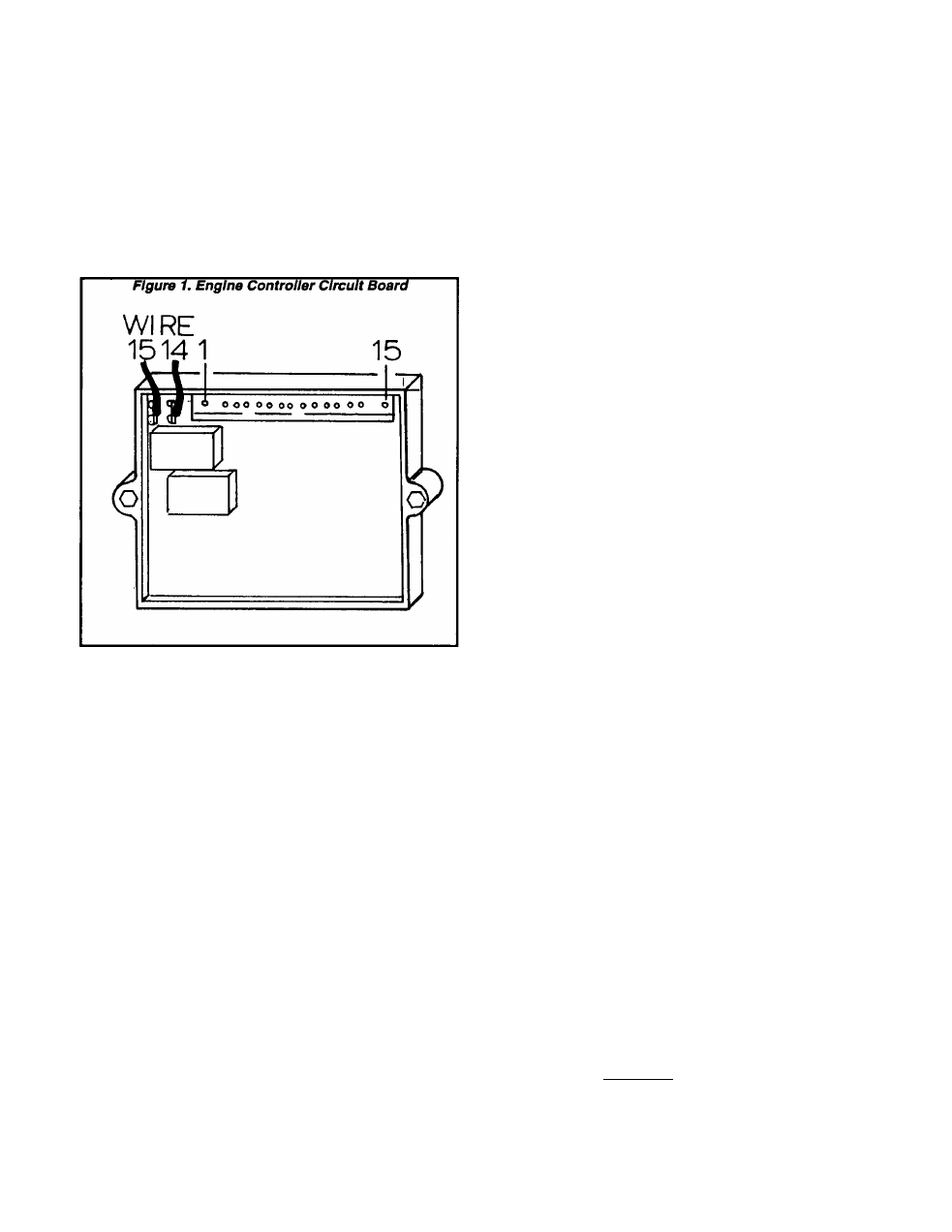
The Enalne Controller circuit board controls all
phases of engine operation, Including cranking,
starting, running ana shutdown.
The circuit board interconnects with other com
ponents of the engine eiectricai system to turn
them on or off at the proper times.
The board is powered by fused 12 VDC battery
output, avaiiabie to the board via Wire 15.
Circuit Board Connections
The circuit board mounts a 15-pin receptacie
(J1). A 15-pin connector piug connects to this re
ceptacle to Interconnect the board with other com
ponents and circuits. In addition, a single pin ter
minal Is provided on the board for connection of
Wire 15 (J3) and a single pin terminal for Wire 14
(J2).
Receptacle J1
This 15-pln receptacle Is shown In Figure 2, along
with a chart that identifies each pin, wire and func
tion.
Receptacle J2
Wire 14 connects to Terminal J2. This terminal
and wire are electrically hot (12 volts DC) only when
the engine is cranking or running. Battery voltage
Is delivered to Terminal J2 when circuit board ac
tion energizes a board-mounted run relay while
cranking or running.
Wire 14 DC output is delivered to (a) the engine
fuel pump and (b) the engine Ignition system. If an
optional remote panel Is used. Wire 14 DC output
will turn on a "RUN" lamp on that panel.
Receptacle J3
wire 15 connects to Terminal J3. This Is fused
battery voltage. The Wire 15 circuit Is electrically
hot at all times (provided the unit battery Is con
nected).
Figure 2. Receptacle J1
10
11
12
13
14
15
WIRE
56
90
18B
17
66
85
18
ToncnsTT
Delivers 12 VDC to Starter Contactor
while cranking only.
Delivers 12 VDC to automatic choke
solenoid coll while cranking only.
Interconnects CCG circuit board so
that board can stop engine In the event
of a generator fault (NOTE 1).
Not used on computer-controlled
generator units.
Not used on computer-controlled
generator units.
When Wire 17 Is connected to ground
by holding Start-Run-Stop switch at
"START", cranking will occur.
Not used on computer-controlled
generator units.
Not used on computer-controlled
generator units.
Not used on computer-controlled
generator units.
AC signal from Stator battery charge
winding for starter cutout.
When grounded by Low Oil Pressure
or High oil Temperature switch, the
circuit board will stop engine.
Common frame ground.
Not used on Computer-controlled
generator units.
When Wire 17 Is connected to ground
by holding Start-Run-Stop switch at
"STOP^'i shutdown will occur.
Not used on computer-controlled
generator units.
NOTE 1:- See "AUTOMATIC SHUTDOWNS" In Section
1.2 (Page 1.2-5).
1
3
5
7
10
12
14
6
9
11
b P P □ □ □ □
o q q q q
A A
13
15
Page 6.2-1