General, Description, Operational check and adjustment – Generac Power Systems NP-40G User Manual
Page 63
Attention! The text in this document has been recognized automatically. To view the original document, you can use the "Original mode".
Section 3,5- AUTOMATIC CHOKE
General
The GN-190 and GN-220 vertical shaft engines
are equipped with an automatic choke. A choke
solenoid is attached to the carburetor choke shaft
by means of a choke control link. Solenoid opera*
tion is controlled by an engine controller circuit
board. The circuit board energizes and de-ener
gizes the solenoid cyclically at a rate dependent on
ambient temperature during engine cranking only.
Description
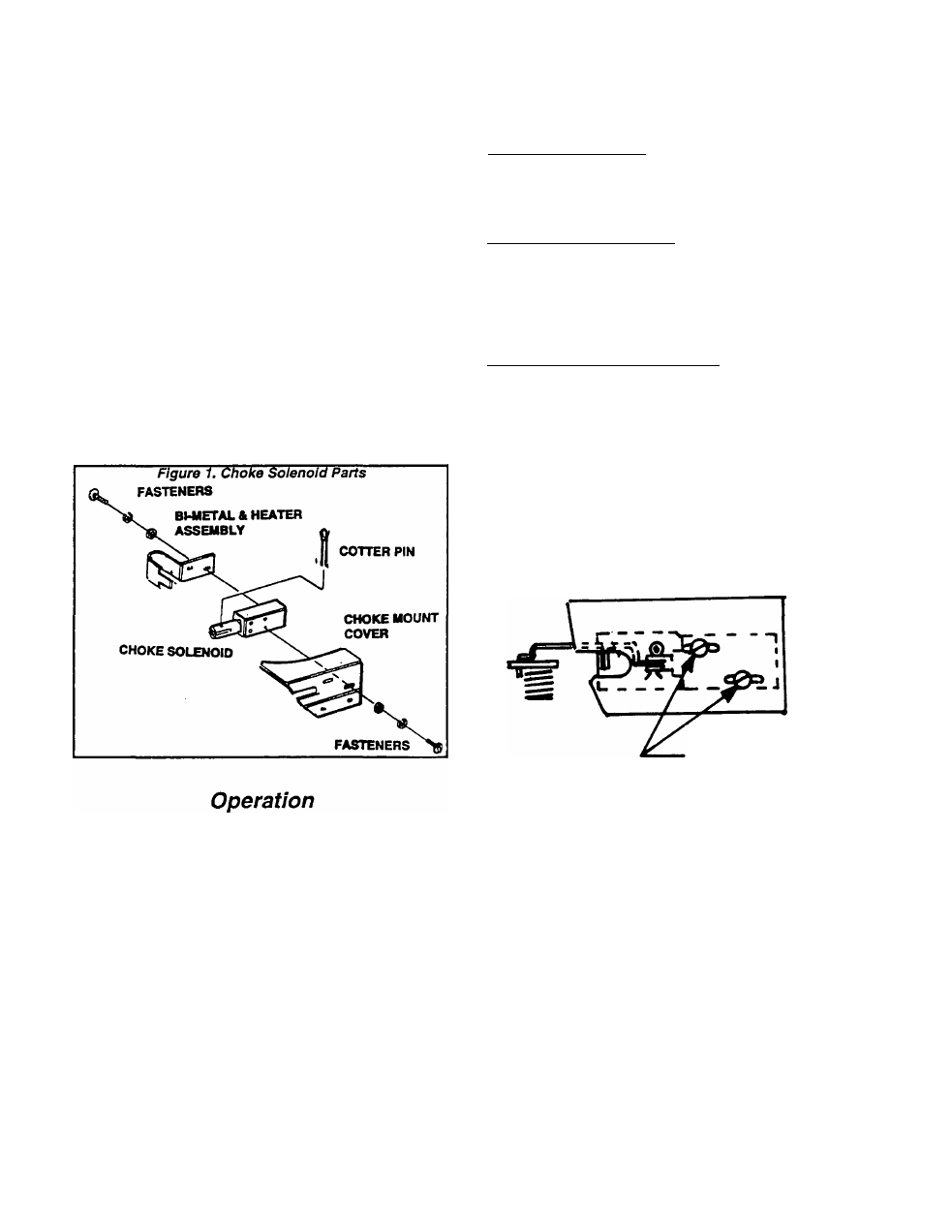
See Figure 1. The CHOKE SOLENOID is retained
to a CHOKE COVER by two No. 4-40 SCREWS,
LOCKWASHERS and FLATWASHERS. The two
screw holes in the COVER are slotted to provide for
axial adjustment of the CHOKE SOLENOID. A COT
TER PIN retains a CHOKE LINK to the SOLENOID.
A CHOKE BI-METAL & HEATER Is retained to the
SOLENOID
by
two
No.
4-40
SCREWS,
LOACKWASHERS and FLATWASHERS.
NOTE: Also see Part 6, "ENGINE ELECTRICAL
SYSTEM". The section on DC control system In
cludes additional Information on choke operation
and the engine controller circuit board.
When the engine Is being cranked, engine con
troller circuit board action energizes the choke
solenoid in regular timed cycles. Each time the
choke solenoid is energized, it closes the carbu
retor choke valve. The circuit board’s choke timer
circuit provides energizes the choke solenoid
(pulls it in) about every 2 to 5 seconds’
When the engine starts, cranking is terminated.
The choke action Is then terminated and the choke
setting is determined by a choke heater (CH).
Operational Check and Adjustment
OPERATIONAL CHECK:
Crank the engine. During cranking, the choke
solenoid should pull in about every 2 to 5 seconds.
If it does NOT pull in, try adjusting the choke.
PRE-CHOKE ADJUSTMENT:
With the solenoid NOT pulled In, the carburetor
choke valve (choke plate) should be about 1/8 inch
from its full open position. If necessary, use needle
nose pliers to bend the tip of the BI-METAL until a
1/8 inch setting is obtained.
CHOKE SOLENOID ADJUSTMENT:
Loosen the two screws that retain the choke
solenoid to Its cover. Adjust axial movement of the
solenoid plunger by sliding the solenoid In the
slotted screw holes of the cover.
Adjust plunger axial movement until (with the
carburetor choke valve closed) the plunger is bot
tomed in the solenoid coil. That Is, until the plunger
is at its full actuated position.
With the choke valve (choke plate) closed and the
plunger bottomed in its coil, tighten the two
screws.
figure 2. Choke Adjustment
Loosen 2 screws and
slide solenoid In the
slots of choke mount
cover. With carburet
or choke plate clos
ed, plunger must
be bottomed In coil.
Page 3.5-1