Introduction, Upper fan housing, Upper cooling fan – Generac Power Systems NP-40G User Manual
Page 11: Permanent magnet rotor
Attention! The text in this document has been recognized automatically. To view the original document, you can use the "Original mode".
Section 1.2- MAJOR GENERATOR COMPONENTS
Introduction
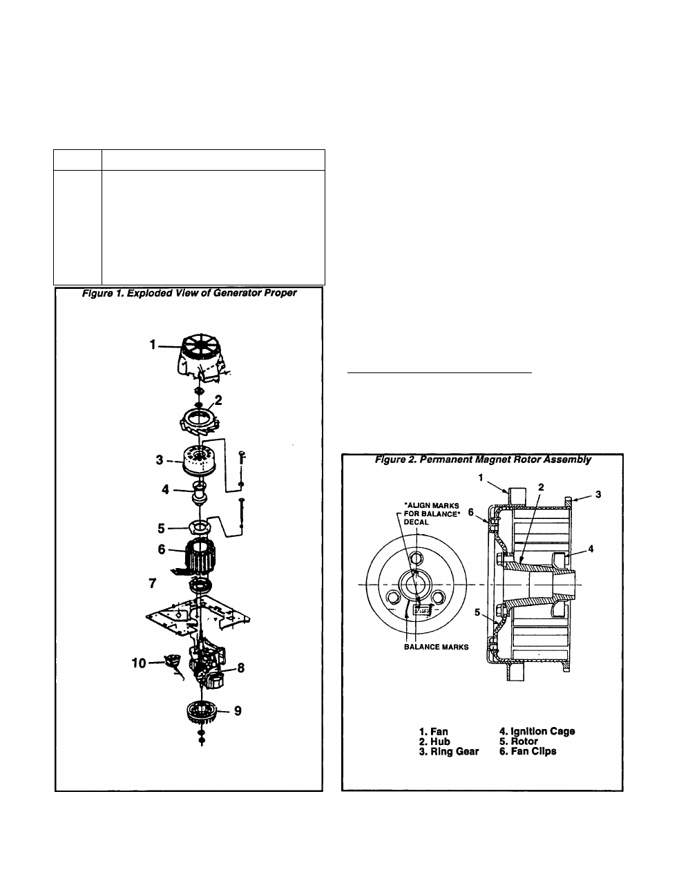
Major components of the generator proper are
shown in Figure 1, beiow. Externai sheet metal and
other unrelated components are omitted from the
drawing for clarity. These parts are:
ITEM
NOMENCLATURE
1
Upper Fan Housing
2
Upper Cooling Fan
3
Permanent Magnet Rotor
4
Rotor Hub
5
Stator Retaining Ring
6
Stator Assembly
7
Stator Adapter
8
Engine
9
Lower Fan & Flywheel
10
Stepper Motor
Upper Fan Housing
As its name implies, this component houses and
shields the upper cooling fan. See Figure 1, Item
1
.
Upper Cooling Fan
The Cooling Fan draws air Into the generator
through slots in the Upper Fan Housing. It Is fas
tened to and rotates with the Permanent Magnet
Rotor.
Permanent Magnet Rotor
Sixteen permanent magnets have been affixed to
the Rotor. A starter ring gear is welded to the
Rotor. The Rotor and Hub are balanced at the fac
tory as an assembly and must be replaced as an
assembly.
NOTE: The hub MUST be properly aligned during
reassembiy. The mounting bolt, housing opening
and magnet must be properly aligned. In addition,
match marks between the Hub and Rotor must be'
aiigned as indicated by an “ALIGN MARKS FOR
BALANCE” decal. During assembiy, use care to
avoid damage to the Ignition Sensor.
______________
DANGERI
THE PERMANENT MAGNET ROTOR PRODUCES
AN
EXTREMELY
STRONG
MAGNETIC
FORCE.
USE CARE DURING INSTALLATION TO AVOID
PINCHED FINGERS.
Page 1.2-1