Valve components removal, Valve train components – Generac Power Systems NP-40G User Manual
Page 38
Attention! The text in this document has been recognized automatically. To view the original document, you can use the "Original mode".
Section 2.2- VALVE TRAIN
Valve Train Components
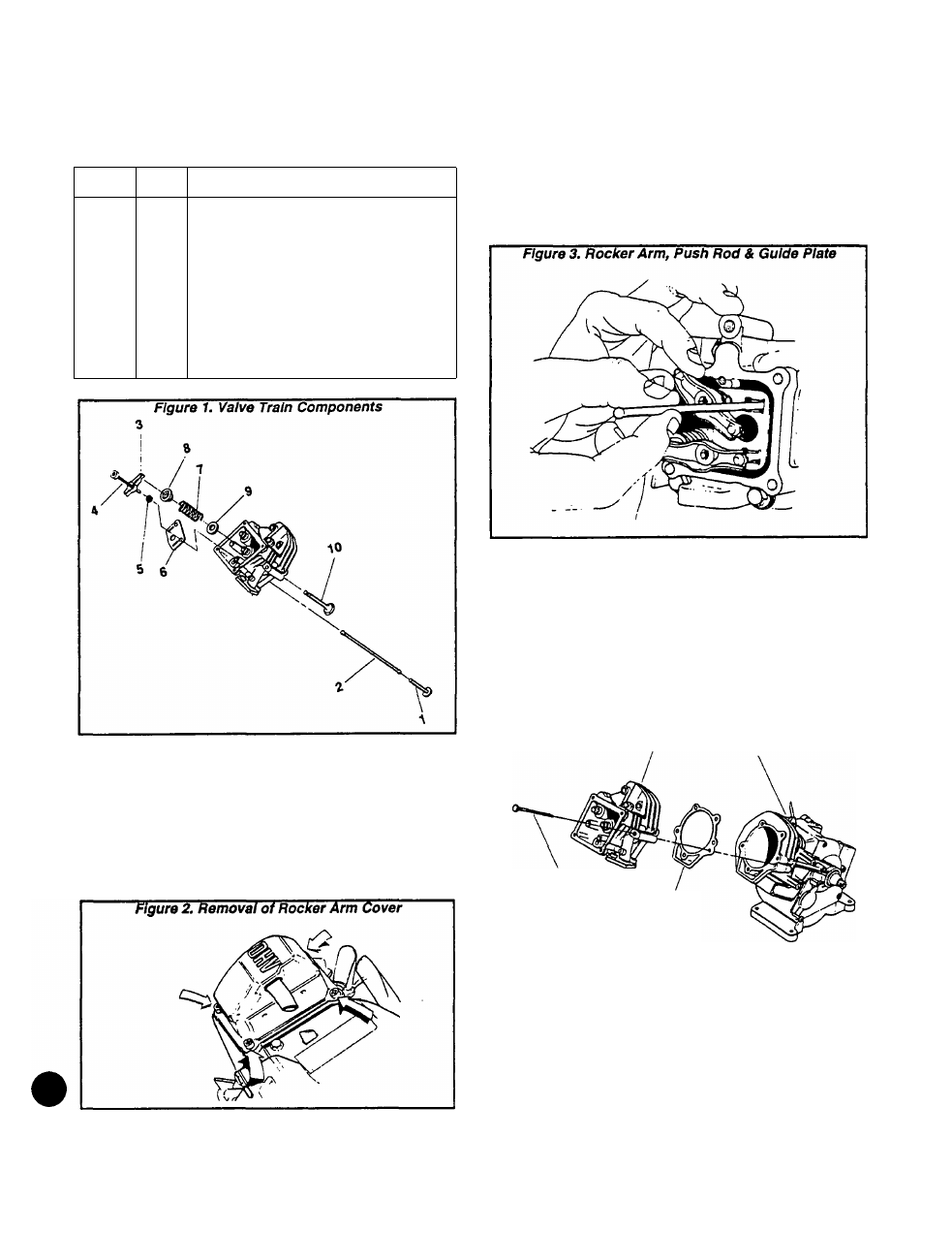
Valve train components are listed below and shown In
Rgure 1, below.
ITEM
QTY
DESCRIPTION
1
2
2
2
Tappet
Push Rod
3
2
Rocker Arm
4
2
Pivot Ball Stud
5
2
Rocker Arm Jam Nut
6
1
Push Rod Guide Plate
7
2
Valve Spring
8
2
Valve Spring Retainer
9
2
Valve Spring Washer
Exhaust Valve
10
1
11
1
Intake Valve
Valve Components Removal
1. The ROCKER ARM COVER Is retained by four M6-1.00
X 12mm screws and lockwashers. Remove the four
screws and lockwashers, then remove the ROCKER ARM
COVER and Its gasket
NOTE: Replace the ROCKER ARM COVER GASKET
each time the COVER Is removed, to ensure proper
sealing.
2.
Loosen the rocker arm Jam nuts on the pivot ball studs.
Then, loosen the pivot ball studs. Remove the two pivot
ball studs, the rocker arms and the Jam nuts. Also remove
the push rod guide plate.
NOTE: Keep the Intake valve and exhaust valve
parts separated. Intake and exhaust parts are Iden
tical. However, once a wear pattern has been estab
lished on these parts their tit will be different.
3. Remove the push rods.
4. Remove the cylinder head bolts, then remove the
cylinder head and head gasket
NOTE: Replace the head gasket every time the head
Is removed. The new head gasket must be free of
nicks and scratches as these could cause leakage.
Figure 4. Cylinder Head Removal
CYLINDER
HEAD
CRANKCASE
CYUNDER
HEAD
BOLTS
HEAD
GASKET
DANGERI
ALWAYS WEAR SAFETY GLASSES WHEN RE
MOVING THE VALVE SPRINGS.
5. See Figure 5, next page. Hold the valve with your
fingers while compressing the spring with your thumb,
then proceed as follows:
Page 2.2-1