Test 1- check 15 amp fuse, Test 3- check power to fuel pump, Test 2- check power to switch – Generac Power Systems NP-40G User Manual
Page 108
Attention! The text in this document has been recognized automatically. To view the original document, you can use the "Original mode".
Section 7.2- ENGINE DC CONTROL SYSTEM
Test 1- Check 15 Amp Fuse
DISCUSSION:
The panel-mounted 15 amp fuse Is connected In
series with the 12 VDC power supply to the engine
DC control system. A blown fuse will prevent en
gine priming, cranking and running.
TEST PROCEDURE:
Push in on fuse holder cap
and turn it counterclockwise to
remove cap and fuse. Check
the fuse visually. If the fuse
metal element has melted
open, replace the fuse.
If the visual check is uncer
tain, use a VOM to check fuse.
RESULTS:
1. If fuse is good
a. And if priming function does not work, go to
Test 2.
b. And if engine will not crank, go to Step 4.
2. If fuse is bad, replace it
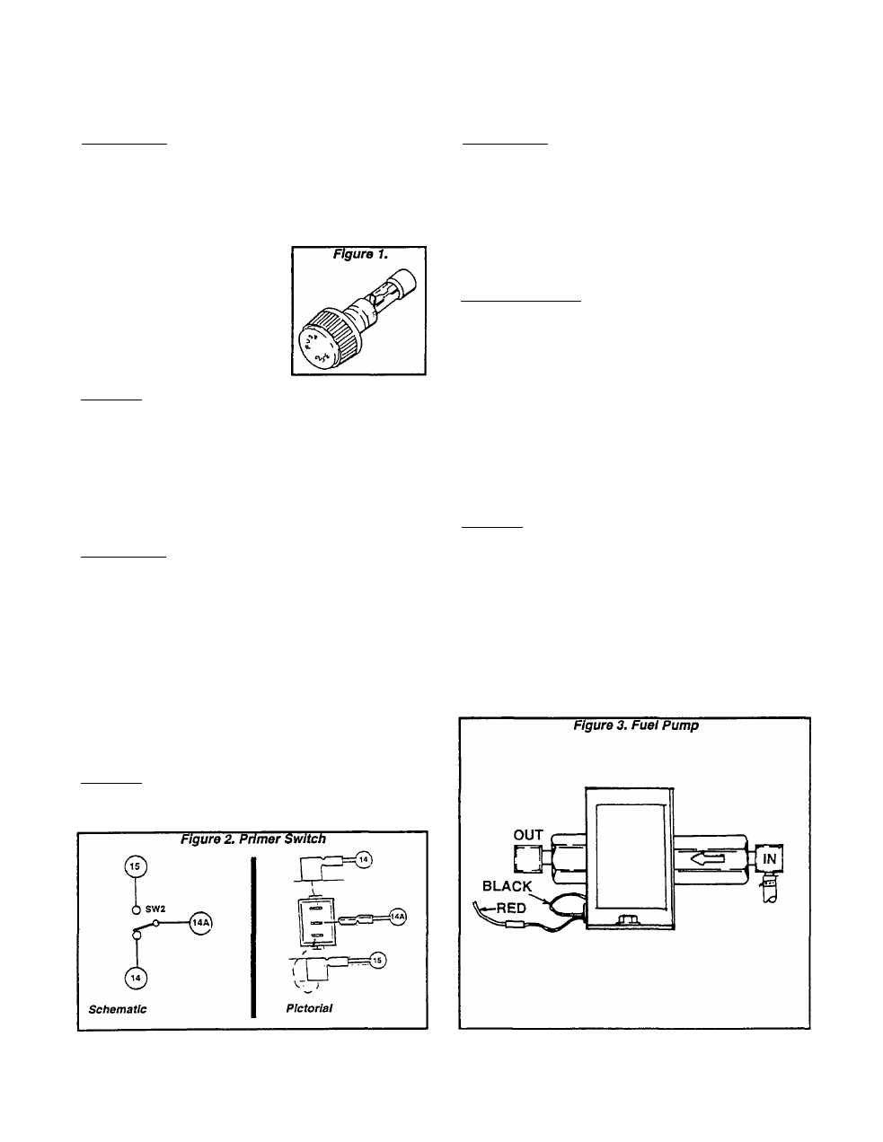
Test 3- Check Power to Fuel Pump
DISCUSSION:
When the rocker type primer switch Is held at
ON", position, fused battery voltage Is delivered to
the electric fuel pump. The pump should then turn
on and prime the carburetor.
During cranking and startup, the engine control
ler circuit board will deliver battery voltage to the
Wire 14 circuit and to the Fuel Pump. The pump
should turn on and run.
TEST PROCEDURE:
Locate the red Wire 14A that connects to the fuel
pump. A wiring connector connects the wires near
the pump. Separate the wire, then check for DC
power as follows:
1. Set VOM to read battery voltage.
2. Connect the VOM test leads across the Wire 14A
from the Primer Switch and frame ground.
3. Hold the Primer Switch at “ON" (Prime). Meter
should read battery voltage.
4.
Hold the panel Start-Run-Stop switch at
“START". The meter should read battery voltage.
Test 2- Check Power to Switch
DISCUSSION:
This is a check of the PRIMER SWITCH on the
panel. When the switch is actuated to its “PRIME"
position, fused battery voltage is delivered directly
to the electric fuel pump on units with gasoline fuel
system. On units with gaseous fuel system, battery
voltage is delivered to the fuel lockoff solenoid.
TEST PROCEDURE:
Set a VOM to read battery voltage (12 VDC).
Connect the meter test leads across the Wire 15
terminal of the Primer Switch and frame ground.
The meter should read battery voltage.
RESULTS:
1. if battery voltage is Indicated, go to Test 3.
2. If battery voltage is NOT Indicated, go to Test 4.
RESULTS:
1. If unit is being tested because the priming func
tion doesn’t work:
a. If battery voltage is good but the pump doesn’t
work, go to Test 5.
b. If battery voltage is NOT indicated, go to Test
6.
2. If engine cranks but will not start:
a. if battery voltage is good but pump doesn’t
work, go to Test 5.
b. If DC power to pump Is good and pump works,
go to Test 22.
Page 7.2-6