Nomenclature and functions, Front – Toa SX-2000 Series Manual User Manual
Page 78
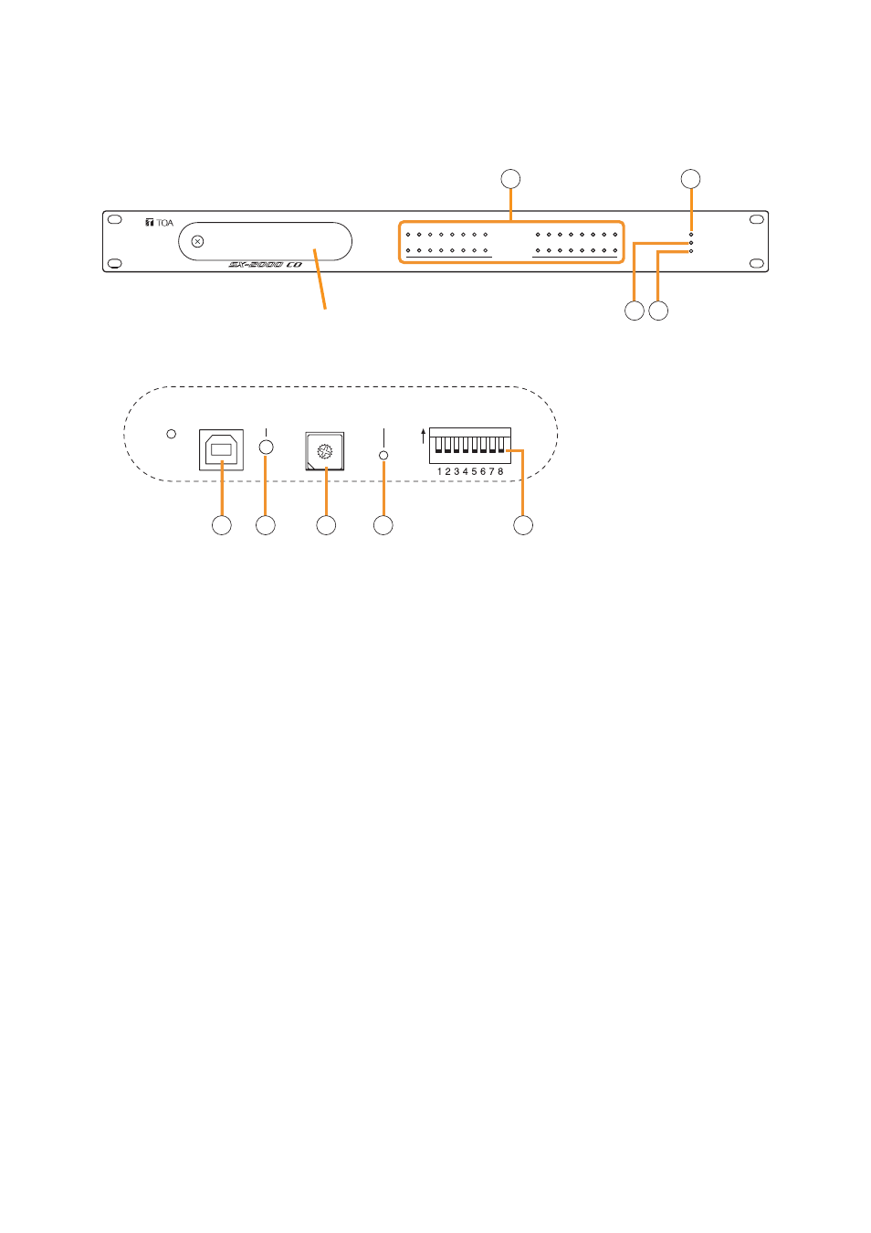
7-2
Chapter 7: SX-2000CO CONTROL OUTPUT UNIT
1. NOMENCLATURE AND FUNCTIONS
[Front]
SETTING
USB
RUN
ID NUMBER RESET
ON
1
9
2
10
3
11
4
12
5
13
6
14
7
15
8
16
POWER
CPU OFF
FAULT
CONTROL OUTPUT UNIT SX-2000CO
17
25
18
26
19
27
20
28
21
29
22
30
23
31
24
32
CONTROL OUTPUT
012
34
56
789AB
CD
EF
Protective cover
Inside of the protective cover
1
2
3 4
5
6
7
8
9
1. Control Output Indicators
[CONTROL OUTPUT 1 – 32] (Green)
Light when the corresponding control outputs are
turned ON.
All indicators are factory-preset to go off because
all control outputs are turned off when the general
urgency all-call is made
By changing the internal DIP switch settings for
the desired control outputs, the corresponding
outputs can be turned ON, making the indicators
light up when the general urgency all-call is made.
(For details, see the separate Installation Manual,
"Installation.")
2. Power Indicator [POWER] (Blue)
Lights when the power is switched on.
3. CPU OFF Indicator [CPU OFF] (Red)
Lights while the general urgency all-call (CPU
OFF state) is being made
4. FAULT Indicator [FAULT] (Yellow)
Lights while general urgency all-call is being made
or when communications to the SX-
2000AO or SX-2100AO are interrupted for 5
seconds or more. Flashes when a failure is
detected in the system.
5. USB Port [USB]
This port is not used.
6. RUN Indicator [RUN] (Green)
Normally flashes continuously.
Goes off while the general urgency all-call is being
made
7. ID Switch [ID NUMBER]
This switch is not used.
Always set to "1."
Note
This switch is set to "1" by default.
8. Reset Key [RESET]
Pressing this key resets the SX-2000CO.
9. DIP Switch [SETTING]
These switches are not used.
Note
Switches 1 – 8 are set to the OFF position by
default.