Nomenclature and functions, Front – Toa SX-2000 Series Manual User Manual
Page 76
6-2
Chapter 6: SX-2000CI CONTROL INPUT UNIT
1. NOMENCLATURE AND FUNCTIONS
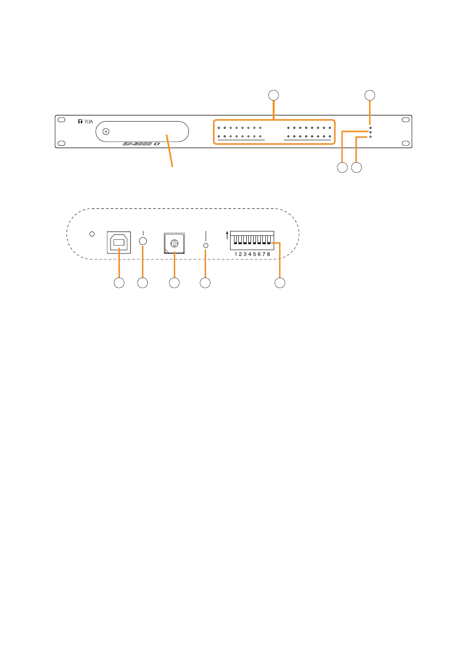
[Front]
Protective cover
Inside of the protective cover
SETTING
USB
RUN
ID NUMBER RESET
ON
1
9
2
10
3
11
4
12
5
13
6
14
7
15
8
16
POWER
CPU OFF
FAULT
CONTROL INPUT UNIT SX-2000CI
17
25
18
26
19
27
20
28
21
29
22
30
23
31
24
32
CONTROL INPUT
012
34
56
789AB
CD
EF
1
2
3 4
5
6
7
8
9
1. Control Input Indicators
[CONTROL INPUT 1 – 32] (Green)
Light when the corresponding control inputs are
turned ON.
2. Power Indicator [POWER] (Blue)
Lights when the power is switched on.
3. CPU OFF Indicator [CPU OFF] (Red)
Lights while the general urgency all-call (CPU
OFF state) is being made
4. FAULT Indicator [FAULT] (Yellow)
Lights while the general urgency all-call is being
made
or when communications to the
SX-2000AO or SX-2100AO are interrupted for 5
seconds or more. Flashes when a failure is
detected in the system.
5. USB Port [USB]
This port is not used.
6. RUN Indicator [RUN] (Green)
Normally flashes continuously.
Goes off while the general urgency all-call is being
made
7. ID Switch [ID NUMBER]
This switch is not used.
Always set to "0."
Note
This switch is set to "0" by default.
8. Reset Key [RESET]
Pressing this key resets the SX-2000CI.
9. DIP Switch [SETTING]
These switches are not used.
Note
Switches 1 – 8 are set to the OFF position by
default.