Nomenclature and functions, Front – Toa SX-2000 Series Manual User Manual
Page 6
1-2
Chapter 1: SX-2000SM SYSTEM MANAGER
Protective cover
Inside of the protective cover
10 11 12
1
2
3
4
5
6
7
8
9
13
14
15 16
18
19
17
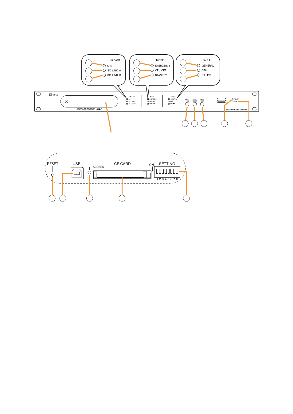
1. NOMENCLATURE AND FUNCTIONS
[Front]
1. LAN Indicator [LAN] (Green)
Lights when the LAN connection terminal on the
rear panel is connected, and flashes during LAN
communications.
2. SX Link A Indicator [SX LINK A] (Green)
Lights when the SX Link A connection terminal on
the rear panel is connected, and flashes while
communications are being performed via the SX
Link A terminal.
3. SX Link B Indicator [SX LINK B] (Green)
Lights when the SX Link B connection terminal on
the rear panel is connected, and flashes while
communications are being performed via the SX
Link B terminal.
4. Emergency Indicator [EMERGENCY] (Red)
Lights while the general urgency all-call is being
made
or when the SX-2000 system is in
an emergency condition, and flashes when a 24 V
emergency cutoff* state occurs involving any SX-
2000AO within the system.
* In the SX-2000 system, a 24 V emergency cutoff
input terminal that allows control of an
emergency audio input is provided on the SX-
2000AO's rear panel. When the SX-2000 system
is combined with another emergency broadcast
system, a 24 V DC is normally kept being
supplied to this emergency cutoff input terminal
and is cut off (24 V emergency cutoff function) in
emergency situations. This interrupts the
general-purpose broadcast from the SX-2000,
allowing the emergency broadcast system to
override it. (For details, see the separate
Installation Manual, "Installation.")
5. CPU OFF Indicator [CPU OFF] (Red)
Lights while the general urgency all-call (CPU
OFF state) is being made
6. Standby Indicator [STANDBY] (Green)
Lights when the SX-2000 system is operating on
the backup power supply during power failures.
It also lights when the system reset cannot be
performed using the SX-2000 Setting software.
Note that if the standby indicator lights, it is not
possible to restart your SX-2000SM using the
Setting software.
To perform system reset, press the Reset key (15)
inside the protective cover to restart.
7. General Indicator [GENERAL] (Yellow)
Lights while the general urgency all-call is being
made
or when a failure is detected in the
SX-2000SM. Lights or flashes when a failure is
detected in the system.