Example of program – KEYENCE LS-3100/3100W Series User Manual
Page 81
75
CHAPTER 6 Optional Interface Boards
When connecting LS controller with external computer
Program
The following settings are specified through the computer: DIA (segment
mode), CH1=X (output channel mode), NORMAL (measurement mode),
MOVE (averaging mode), 512 (the number of measurements for averaging).
Then, the measured value is displayed once on the computer.
100
ISET IFC
110
CMD DELIM=0
120
WBYTE &H3F, &H41, &H20, &H4;
130
PRINT @0;"D"
140
PRINT @0;"C0"
150
PRINT @0;"MN"
160
PRINT @0;"A9"
170
PRINT @0;"BM"
180
PRINT @0;"X0"
190
LINE INPUT @0;A$
200
PRINT A$; "mm"
210
END
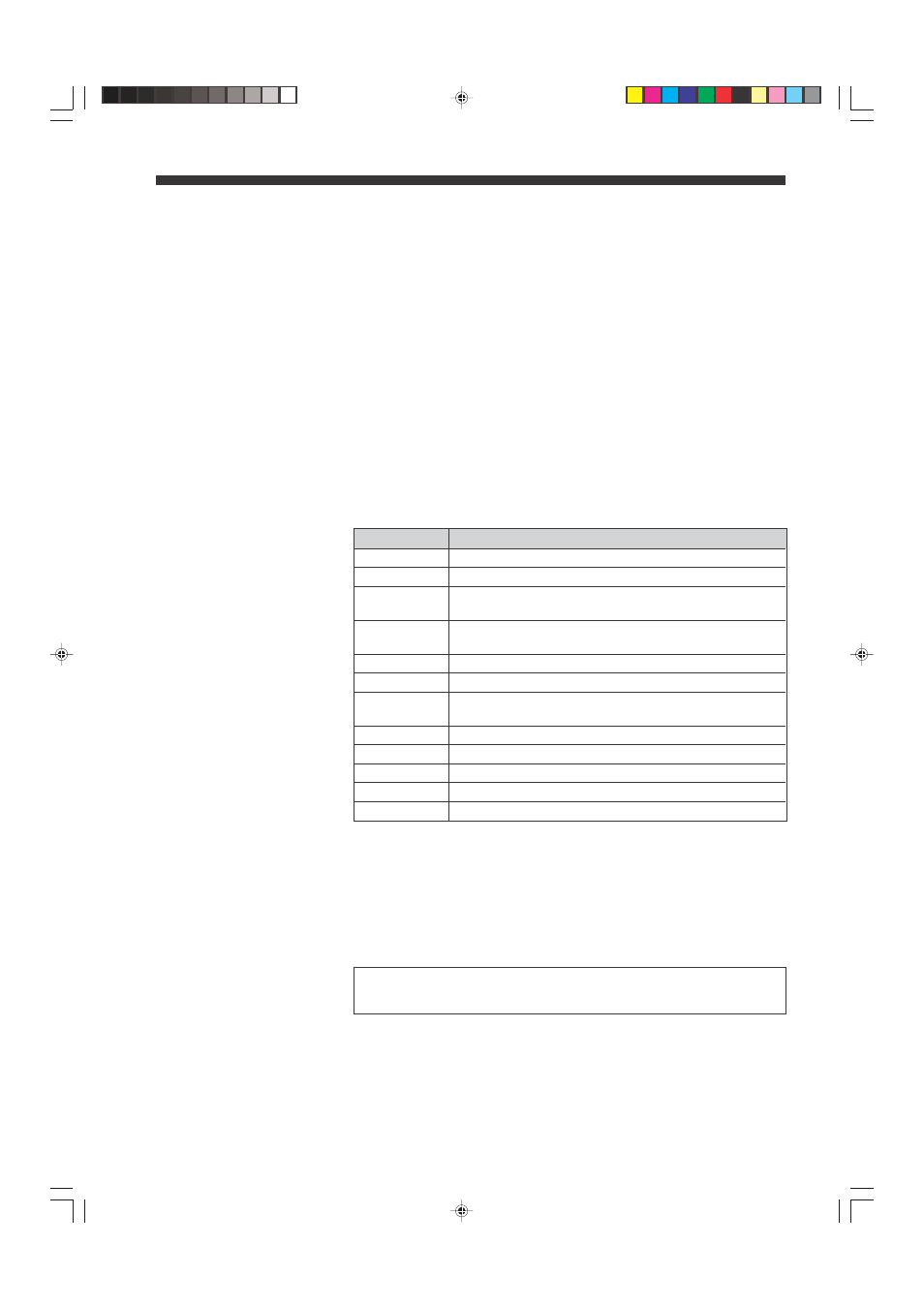
Program line#
Description
100
Clears interface.
110
Sets delimiter to "CR +LF".
120
Sets talker address for PC to "1".
Sets listener address for LS controller to "0".
130
Transmits commands to LS controller.
"D": Sets "DIA" as segment mode.
140
"C0": Sets "CH1=X" as output channel mode.
150
"MN": Sets NORMAL as measurement mode.
160
"A9": Sets 512 as the number of measurements for
averaging.
170
"BM": Sets MOVE as averaging mode.
180
"X0": Allows LS controller to output measured value once.
190
Receives measured value once from LS controller.
200
Displays measured value.
210
Terminates program.
The above program provides the following status:
Talker address for PC: 1
Listener address for LS controller: 0
Delimiter sent from LS controller: CR + LF
Talk only mode of LS controller: OFF
Take the following precautions when using the LS controller.
Be sure to turn OFF the power of the LS controller to set the address or
delimiter using the DIP switches on the back panel.
Example of Program
08.10.1, 10:57 AM
75