2 gp-ib interface i/o, Specifications, Pin assignment – KEYENCE LS-3100/3100W Series User Manual
Page 76: 2. gp-ib interface i/o
70
When EXT TRIG IN is pulled low with ETE IN pulled low, the measured value
is output after a max. of 20 ms (MOVE averaging, number of measurements
for averaging: 16 to 1,024), or a max. of "2.5 ms x number of measurements
for averaging" (SIMPLE averaging). The output value is retained until
EXT TRIG IN is pulled low again.
External Trigger Input
(EXT TRIG IN)
6-2. GP-IB Interface I/O
Specifications
The GP-IB I/O interface conforms to IEEE (Institute of Electrical and Elec-
tronics Engineers) standard 488-1978.
Transmission code
Logic level
Number of connectable devices
Total cable length
Cable length between 2 devices
ASCII
15 max. (including controller)
20 m max.*
4 m max.
*
Varies according to the number of interconnected devices.
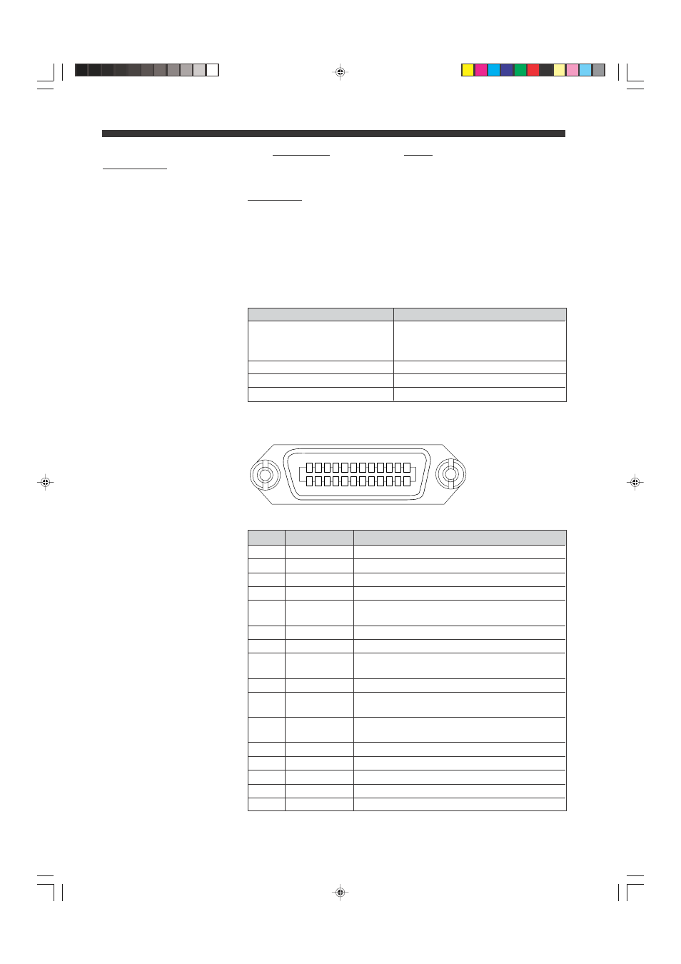
Pin Assignment
Pin No.
Signal
Function
1
DIO1
Data bus
2
DIO2
Data bus
3
DIO3
Data bus
4
DIO4
Data bus
5
EOI
Indicates that the data transmission is
completed.
6
DAV
Indicates that the data is valid.
7
NRFD
Indicates that the data reception is impossible.
8
NDAC
Indicates that the data reception is not
completed.
9
IFC
Initializes the interface.
10
SRQ
Allows devices on the line to request interrupt to
the controller.
11
ATN
Determines whether the data is interface
message or device message.
12
Shield
Shield
13
DIO5
Data bus
14
DIO6
Data bus
15
DIO7
Data bus
16
DIO8
Data bus
CHAPTER 6 Optional Interface Boards
Logic 0 (HIGH state): +2.4 V min.
Logic 1 (LOW state): +0.4 V max.
(Bidirectional transceiver is used.)
(To be continued)
12 11 10 9 8 7 6 5 4 3 2 1
24 23 22 21 20 19 18 17 16 15 14 13
08.10.1, 10:57 AM
70