Chapter 6 optional interface boards, 1 bcd output, Specifications – KEYENCE LS-3100/3100W Series User Manual
Page 74: Pin assignment, Chapter 6, Optional interface boards, 1. bcd output, Ptional, Nterface, Oards
68
CHAPTER 6
O
PTIONAL
I
NTERFACE
B
OARDS
6-1. BCD Output
The optional interface boards shown in this chapter can be factory-attached
by the manufacturer at your request.
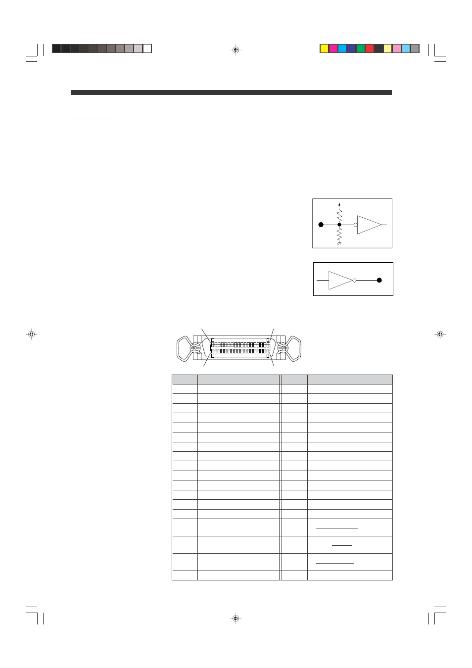
Specifications
Input
TTL voltage level, negative logic
(74LS19 or equivalent)
Output
TTL voltage level, positive logic
(74LS04 or equivalent)
Pin No.
Signal
Pin No.
Signal
1
BCD output: 10
-4
(1)
19
BCD output: 10
0
(4)
2
BCD output: 10
-4
(2)
20
BCD output: 10
0
(8)
3
BCD output: 10
-4
(4)
21
BCD output: 10
1
(1)
4
BCD output: 10
-4
(8)
22
BCD output: 10
1
(2)
5
BCD output: 10
-3
(1)
23
BCD output: 10
1
(4)
6
BCD output: 10
-3
(2)
24
BCD output: 10
1
(8)
7
BCD output: 10
-3
(4)
25
BCD output: 10
2
(1)
8
BCD output: 10
-3
(8)
26
BCD output: 10
2
(2)
9
BCD output: 10
-2
(1)
27
BCD output: 10
2
(4)
10
BCD output: 10
-2
(2)
28
BCD output: 10
2
(8)
11
BCD output: 10
-2
(4)
29
BCD output: 10
3
(1)
12
BCD output: 10
-2
(8)
30
BCD output: 10
3
(2)
13
BCD output: 10
-1
(1)
31
BCD output: 10
3
(4)
14
BCD output: 10
-1
(2)
32
BCD output: 10
3
(8)
15
BCD output: 10
-1
(4)
33
Strobe output signal
(STROBE OUT)
16
BCD output: 10
-1
(8)
34
External trigger enable
input (ETE IN)
17
BCD output: 10
0
(1)
35
External trigger input
(EXT TRIG IN)
18
BCD output: 10
0
(2)
36
GND
Pin Assignment
+5V
3K
6.2K
I C
I N
Ω
Ω
I C
OUT
H
I
1
Z
08.10.1, 10:57 AM
68