KEYENCE LS-3100/3100W Series User Manual
Page 56
50
CHAPTER 4 Functions and Controls
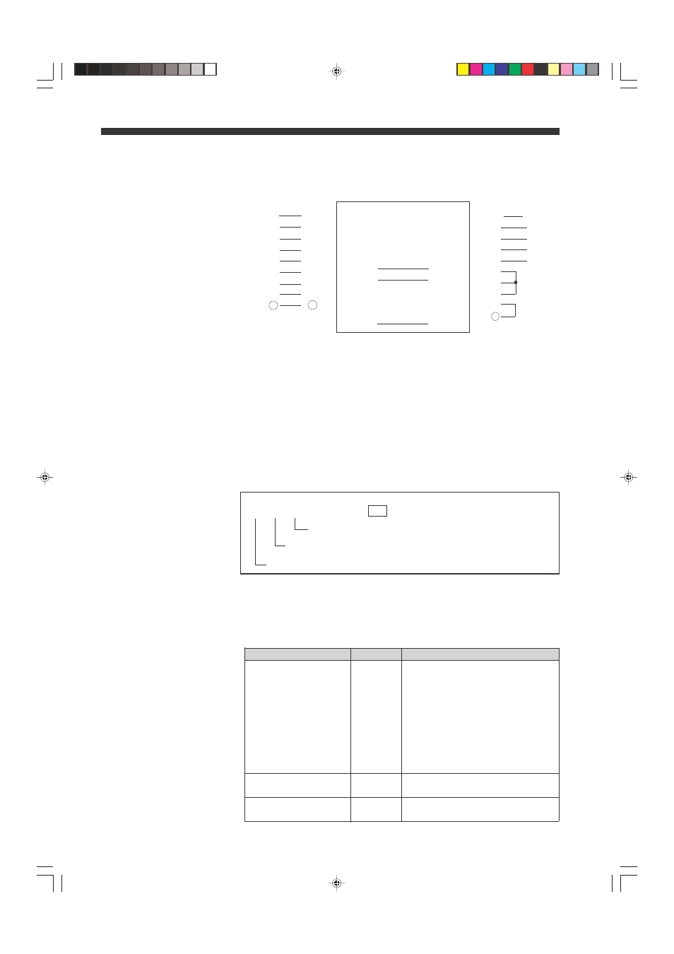
Connector Pin Assignment
In addition to the pin connec-
tions shown here, all identi-
cally-numbered pins of PC
and LS controller can be
connected.
1
1
2
2
.
.
.
.
.
.
O
O
Remote Operation
The settings and data output can be performed using external equipment
such as a computer, instead of the front panel keys of the LS controller. This
operation method is referred to as remote operation. The items which can be
remotely operated are divided into four sections (setting of measurement
conditions, setting of output conditions, output of measurement data and
output of setting status), and are described in the following.
"Format" used in the following description means input form.
Setting Measurement
Conditions
Set the measurement conditions for the desired program. The format differs
with the setting item, as described below.
Format:
([P$] [S$] [H$] ) [COMMAND] CR
Note that one or more of the commands in ( ) can be omitted.
When [P$] is omitted, the current program No. will be valid.
When [S$] is omitted, the current segment selector will be valid.
When [H$] is omitted, the current scanning head will be valid.
Program No.
Segment No. (Segment Selector)
Head No. (Scanning head No.)
Function
Command
Description
Specifying [P$]
P1
Specifies program No. 1
(Program No.)
P2
Specifies program No. 2
P3
Specifies program No. 3
P4
Specifies program No. 4
P5
Specifies program No. 5
P6
Specifies program No. 6
P7
Specifies program No. 7
P8
Specifies program No. 8
P9
Specifies program No. 9
PA
Specifies program No. 10
Specifying [S$]
X
Specifies segment selector X
(Segment selector)
Y
Specifies segment selector Y
Specifying [H$]
1
Specifies scanning head No. 1
(Scanning head No.)
2
Specifies scanning head No. 2
[P$] [S$] [H$] List
Use straight type cable.
Connection example 1
Connection example 2
Pin No.
Pin No.
Pin No.
Pin No.
(PC)
(LS)
(PC)
(LS)
1
1
1
1
2
2
2
2
3
3
3
3
5
5
7
7
6
6
4
7
7
6
8
8
8
20
20
5
20
08.10.1, 10:56 AM
50