Banner SureCross DX80 Wireless Networks User Manual
Page 24
Parameters
Action
Select an action from the following: None, Reads
From, or Writes To. Select None to perform no
action, Reads From reads the parameter from
the remote register and copies the contents into
the local register, and Writes To writes the data
from the local register to the remote register.
Get
Click the Get button to read all device and I/O
parameters from the DX80 device and load them
into the Web Configurator screens. This does not
save the parameters to the XML file.
Local
Regis-
ter
The Local Register entry is the from register in
the I/O mapping. I/O points are linked from the
local register to the remote register.
Map
Num-
ber
Each map entry is defined with a map number,
one through 32. The master table entries define
the register-to-register communication for remote
I/O points. Each line represents a register/point
connection to another Modbus slave device. Up
to 32 table entries are possible.
Poll
Time-
out
The poll timeout refers to the time limit, in milli-
seconds, to communicate with a specific slave
device. When this time limited is exceeded, the
system begins communicating with the next de-
vice in the table. The Poll Timeout setting pre-
vents the system from stopping when a slave de-
vice is not responding.
Re-
fresh
Click the Refresh button to refresh the screen im-
age. This updates any information on the screen
that may have changed on the device.
Re-
mote
Regis-
ter
The Remote Register entry is the to register in
the I/O mapping. I/O points are linked from the
local register to the remote register.
Re-
mote
Type
Select a type from the following drop-down list:
none, coil (output), discrete input, input register,
or holding register. DX80 device registers are all
holding registers. Banner Engineering’s Sure-
Cross™ slave devices use only input registers
and holding registers. When using slave devices
from other manufacturers, please refer to the
manufacturer’s documentation to determine what
I/O types they use.
Coil (output). 1xxxx - Other slave devices, write
only, 1 bit
Discrete Input. 3xxxx - Other slave devices,
read only, 1 bit
Input Register. 3xxxx - SureCross™ slave devi-
ces, read only, 16 bit
Reset
The Reset button resets any error conditions
displayed. Until the error message is reset, the
device will not start any additional operations.
Slave
ID
The slave ID is an identifying number used for
devices within a Modbus system. By default,
Gateways are set to Modbus Slave ID 1. When
using more than one Modbus slave, set each
slave to a unique ID number.
Thresh-
old and
Hyste-
resis
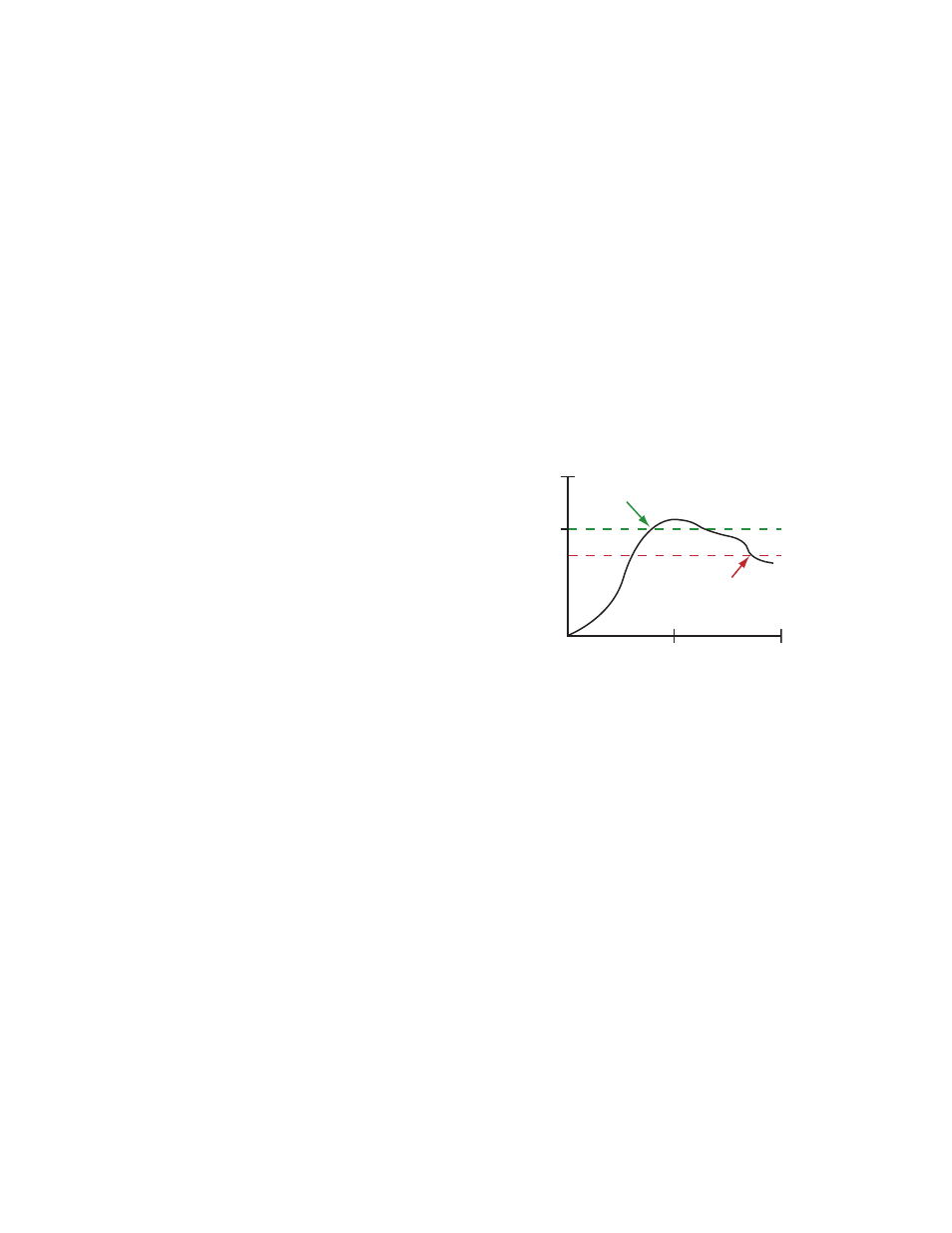
Threshold and hysteresis work together to es-
tablish the ON and OFF points of an analog in-
put. The threshold defines a trigger point or re-
porting threshold (ON point) for a sensor input.
The hysteresis value establishes how much be-
low the active threshold (ON point) an analog in-
put is required to be before the input is consid-
ered OFF. A typical hysteresis value is 10% to
20% of the unit’s range.
Threshold
ON point
Time
Input V
alue
Input
Hysteresis
OFF point
In the example shown graphically, the input is
considered on at 15 mA. To consider the input
off at 13 mA, set the hysteresis to 2 mA. The in-
put will be considered off when the value is 2
mA less than the threshold.
SureCross Web Configurator
24
www.bannerengineering.com - tel: 763-544-3164
rev. -