Test for fault location, Interpreting the fault location measurement, Figure 33 fault location measurement screen – Bird Technologies SA-6000XT-Manual User Manual
Page 55
39
Test for Fault Location
1.
Connect the Site Analyzer to the cable being tested.
Note: If the Site Analyzer is calibrated with a phase stable cable con-
nected to its antenna port, do not remove the cable. Connect it to the
cable to be tested.
2.
Wait at least 10 seconds for the sweep to update.
3.
When a trace is on the screen, do any of the following:
Hold the trace. See “Measurement Hold” on page 51.
Add markers to the trace. See “Markers” on page 52.
Save the trace. See “Saving a Trace” on page 58.
Interpreting the Fault Location Measurement
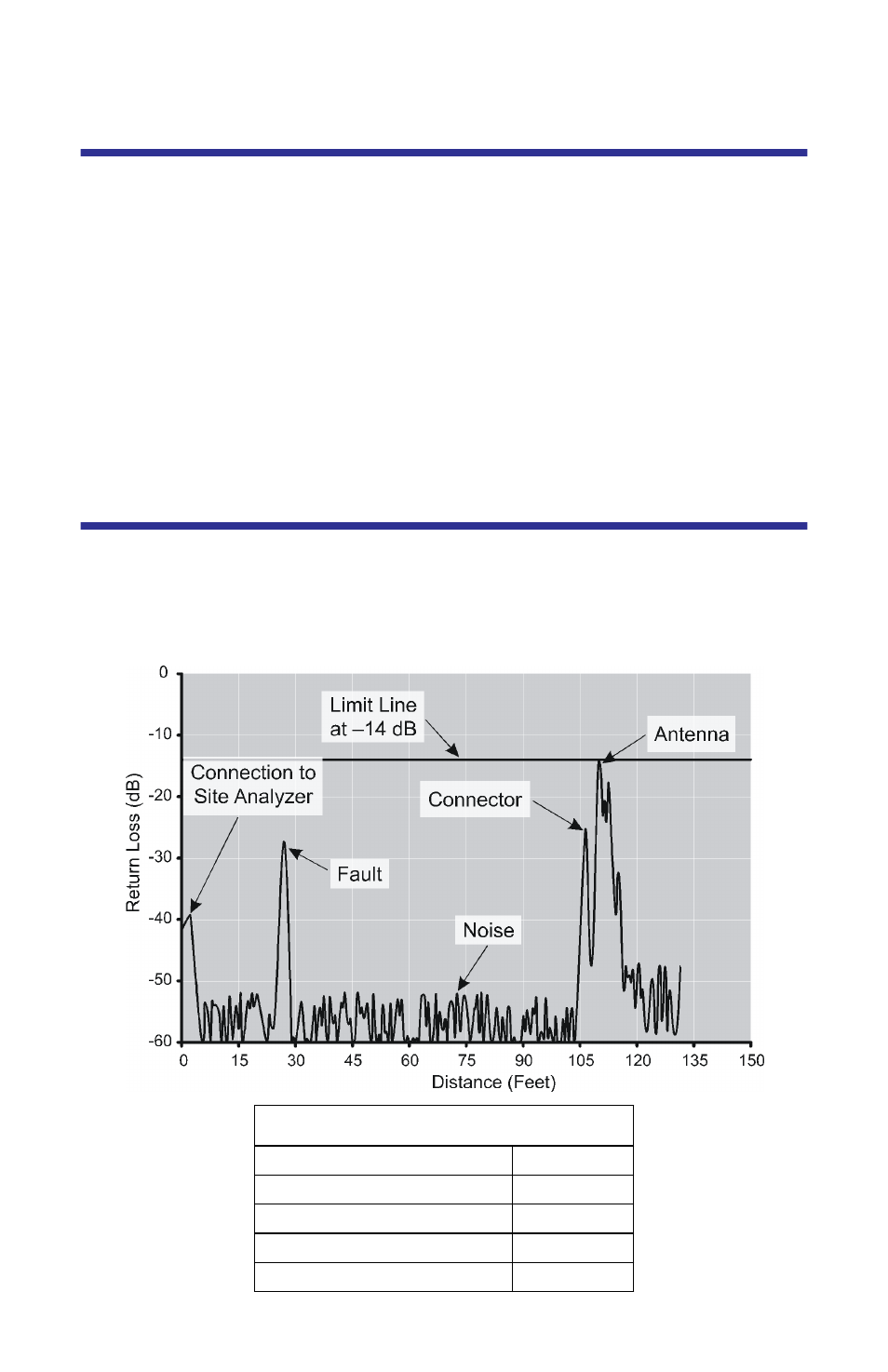
The graph below shows a typical Fault Location measurement for an antenna
system. The table lists typical component return losses.
Figure 33 Fault Location Measurement Screen
Typical Component Return Loss
Antenna at Resonance
–14 dB
Connector
–25 dB
Jumper
–35 dB
Lightning Protector
–25 dB
Transmission Line
–30 dB