Chapter 3 measure match mode, Determine the power of the component being tested, Selecting the measure match mode – Bird Technologies SA-6000XT-Manual User Manual
Page 29: Figure 9 selecting the measure match mode
13
Chapter 3
Measure Match Mode
Match measurement verifies and monitors the match conditions in the antenna
system at various frequencies. The results are shown on an x-y graph. Frequency
is shown on the x-axis and return loss, cable loss, or VSWR is shown on the y-axis.
Before making a match measurement, be sure to have a Bird Calibration Combi-
nation (Cal Combo) and all necessary cables and adapters of the correct size and
connector type.
This chapter describes how to make a match measurement and provides step by
step instructions. In addition, this chapter describes how to set and move mark-
ers. For information and instructions to save and recall traces, refer to Saving
and Recalling Traces, page 56.
To make a match measurement, follow the procedures in this chapter in the
order they are presented.
Determine the Power of the Component Being Tested
Use a service monitor, power meter, or spectrum analyzer to check that the com-
ponent being tested does not have power greater than +22 dBm.
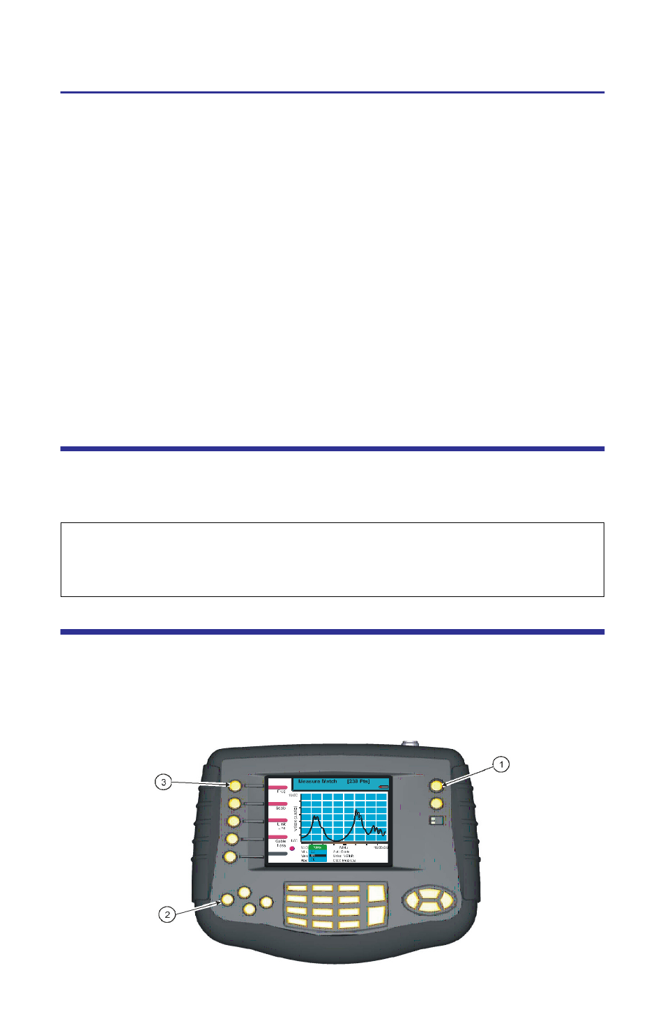
Selecting the Measure Match Mode
1.
Press ON/OFF key for ½ second.
2.
Press the Mode key.
3.
Press the Measure Match key.
Figure 9 Selecting the Measure Match Mode
CAUTION
+22 dBm max. input
Do not apply RF power to Antenna Test Port. Exceeding the maximum input
will damage the Site Analyzer.