Site analyzer display screen, Display description, Figure 7 displays – Bird Technologies SA-6000XT-Manual User Manual
Page 26
10
Site Analyzer Display Screen
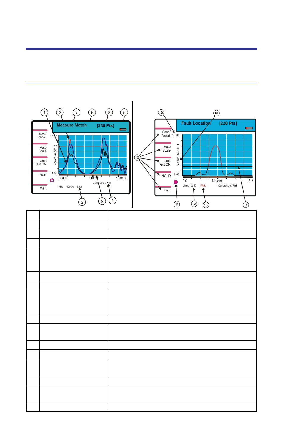
See the following two figures and the accompanying table for a description of the
display screen components for Measure Match mode and for Fault Location mode.
Display Description
Figure 7 Displays
1
Trace
Graphic display of the measurement.
2
Marker Value
Indicates the position and value of a trace point.
3
Marker Cursor
Identifies the trace point displayed in the marker value.
4
Calibration Indicator Indicates the calibration status.
5
Battery Gauge
Indicates whether the Site Analyzer is using the
internal battery or an external power supply, and
indicates the amount of battery life remaining.
6
Recalled Trace Name Indicates the name of a recalled trace.
7
Mode Indicator
Name of the current mode.
8
Measurement Data
Points
Indicates the number of datapoints collected for each
trace. 238 = standard, 475 = twice as many data points
as 238, 949 = four times as many data points as 238.
9
Progress Bar
Indicates data collection progress
10 Softkey Description
Describes the function of the softkey to the left of
the description.
11 Indicator Ball
Indicates if the trace is sweeping.
12 Limit Line Value
Indicates the limit value.
13 Limit Test Indicator
Displays FAIL if any part of the trace exceeds the
limit value.
14 Limit Line
A horizontal line that graphically displays the limit value.
15 Scale
Indicates the minimum and maximum values
displayed on that axis.
16 Units
Indicates the measurement units for that axis.
Measure Match Sample Display
Fault Location Sample Display