Complete your sensor configuration – Rockwell Automation 1771-QDC, D17716.5.93(Passport) PLASTIC MOLDING MODULE User Manual
Page 52
Configure the QDC Module's I/O
Chapter 3
3-8
Follow this procedure to actuate the ram (screw), clamp, and ejector:
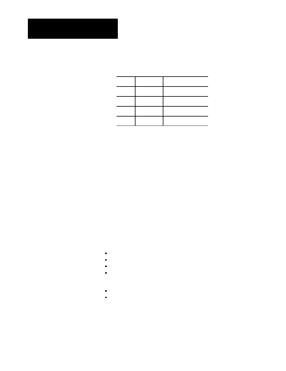
1. Enter values in words DYC09-12 that result in no motion.
Output:
In Data Word:
At ProĆSet 600 Address:
1
DYC09
N40:121
2
DYC10
N40:122
3
DYC11
N40:123
4
DYC12
N40:124
2. Enable set-output operation by entering a 1 in DYC01-B08
(B34/392). The QDC module sets outputs 1-4 to percentage values
that you entered in DYC09-12 respectively.
Important: The DYC is constantly transferred to the QDC module by
Pro-Set 600 software, so changes you make to %-output values are
immediately implemented.
3. With your programming terminal, slowly change the %-output value
of each output, one at a time, as you observe the corresponding
actuator movement.
4. Increase the %-output value until you reach a safe actuator speed to
use in the next procedure.
Complete the procedure for configuring the QDC module to match its
sensors by spanning them over their intended range with the machine in
operation. Here we describe how you determine:
ram (screw) position sensor values
system pressure sensor values
clamp position sensor values
ejector position sensor values
In the procedures that follow, measure and record:
min/max positions and corresponding signal values
min/max system pressure and corresponding signal values
After determining these values from the procedures, write them down on
Worksheet 3-E.
Important: You must complete this configuration before proceeding to
any other chapters on module configuration.
Complete your Sensor
Configuration