Install the qdc module chapter 2 – Rockwell Automation 1771-QDC, D17716.5.93(Passport) PLASTIC MOLDING MODULE User Manual
Page 40
Install the QDC Module
Chapter 2
2-8
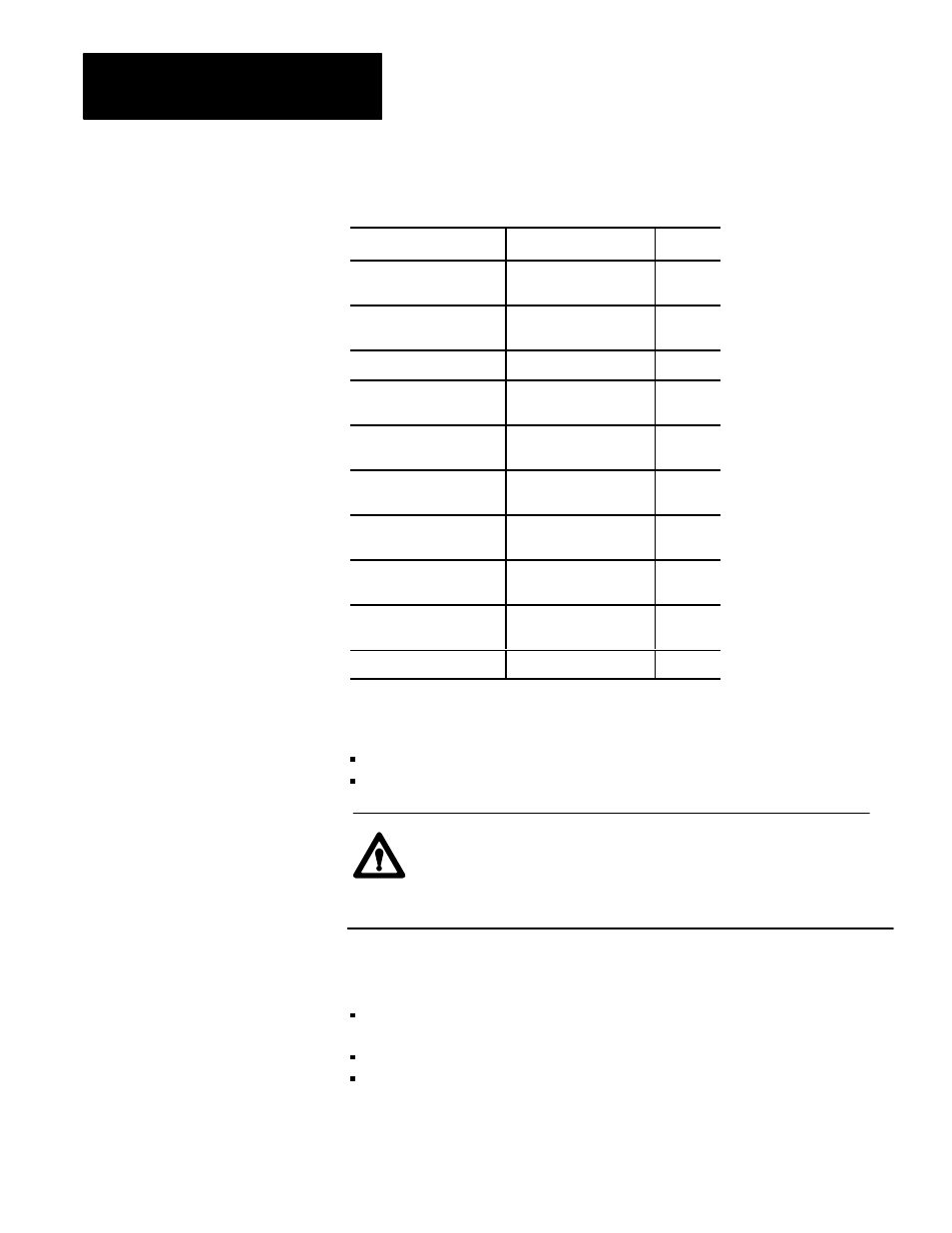
Table 2.B
I/O Terminal Designations
Transducer:
I/O Designation:
Terminal:
Screw position
(see Important below)
Input 1 (+)
(-)
18
17
System pressure
(see ATTENTION below)
Input 2 (+)
(-)
16
15
N/A
Input common
14
Clamp position
(see Important below)
Input 3 (+)
(-)
13
12
Ejector position
(see Important below)
Input 4 (+)
(-)
11
10
Valve 1
Output 1 (+)
Output common
09
08
Valve 2
Output 2 (+)
Output common
07
06
Valve 3
Output 3 (+)
Output common
05
04
Valve 4
Output 4 (+)
Output common
03
02
Not used
01
Important: For the QDC module to operate in the inject, clamp, and eject
mode, you must connect position sensors to these two inputs:
input 1 (screw position)
input 3 (clamp position)
ATTENTION: Your control system may not work as expected
with possibly machine damage if you attempt to control a
pressure profile of a phase (inject, clamp, or eject) not
hydraulically plumbed for pressure control.
Because system pressure may change from one phase to the next, we
recommend that you:
assign pressure control to phases that require pressure profiles
(and are hydraulically plumbed to support it)
place the system pressure sensor accordingly in the hydraulic circuit
configure the remaining phases with velocity profiles