Rockwell Automation 1771-QDC, D17716.5.93(Passport) PLASTIC MOLDING MODULE User Manual
Page 51
Configure the QDC Module's I/O
Chapter 3
3-7
To finish configuring the QDC module, you actuate the ram (screw),
clamp, and ejector axes with the QDC module’s set-output operation that
applies percentage values to your QDC module’s outputs to move the
actuator in a controllable fashion. To do this, you apply a %-output signal
to a module output so you can move the actuator over its intended range.
ATTENTION: Do not rely on pressure valves connected to the
QDC module for pressure relief. Use them only for pressure
control below the setting of the system pressure-relief valve.
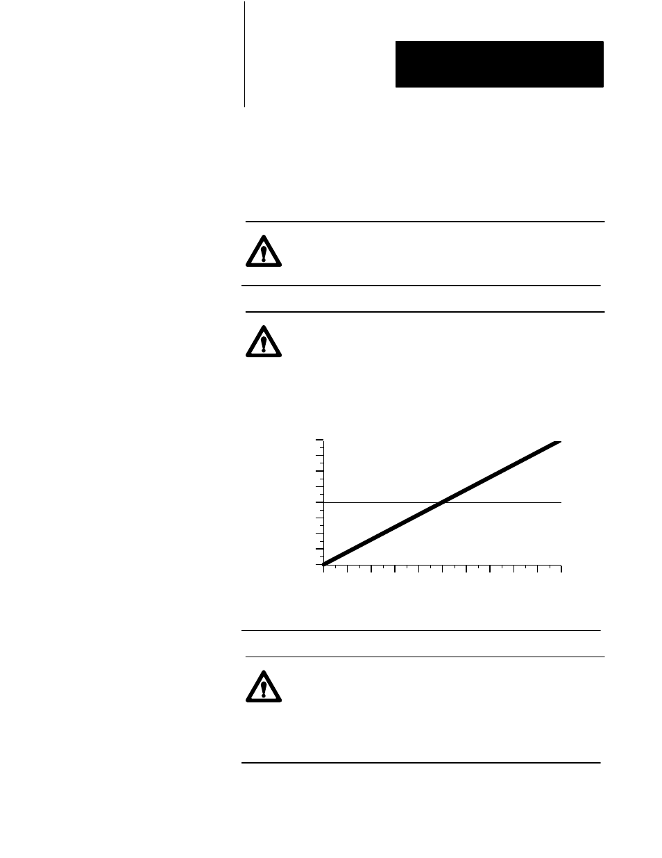
ATTENTION: A value of zero in set-output words
N40:121-124 does not necessarily correspond to zero pressure
or flow. If you configured jumpers E11, E12, E15, or E16 for
bi-directional valve operation, an output of 0% gives –10V dc,
50% gives 0V dc (see chart). Amplifier electronics or
spool-null offsets may also allow pressure or flow at zero volts
signal input. Consult your valve and amplifier specifications.
% Output Requested
Output V
oltage
-10
-8
-5
-3
0
3
5
8
10
0
10 20 30 40 50 60 70 80 90 100
ATTENTION: As soon as you enable set-output operation, the
QDC module’s outputs drive the connected valves according to
the values you entered into DYC09-12 (N40:121-124). Be sure
these values RESULT IN NO MOVEMENT until you adjust
them one-at-a-time with your programming terminal in the
procedures that follow.
Use SetĆoutput Operation to
Move the Ram (screw),
Clamp, and Ejector