Rockwell Automation 1771-QDC, D17716.5.93(Passport) PLASTIC MOLDING MODULE User Manual
Page 249
Tune Your Machine
Chapter 10
10-21
IPC57 – Ram Pressure Limit for Pressure-limited Velocity Control.
When ram (screw) pressure reaches this limit and IPC58 and 59 allow it,
the QDC module switches control from velocity to pressure control.
Consider the following when determining this setpoint. Use a value:
considerably below the mold flash point to let the QDC module
gain pressure control before flashing the mold
less than the injection transition pressure in IPC62
The QDC module may switch back and forth between velocity and
pressure control excessively. To guard against this condition, you can use
setpoints IPC58 and IPC59.
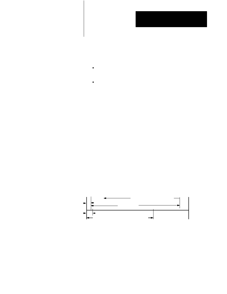
IPC58 – Start of Zone for Pressure-limited Velocity Control.
This position defines the zone measured from mold end in which the QDC
module allows a change from velocity to pressure control (figure 10.2).
Pressure limiting can occur after the ram (screw) passes this position. We
recommend a distance of about 50% of shot size. Smaller distances
increase the possibility of flashing the mold.
IPC59 – Time Delay for Pressure-limited Velocity Control.
This delay starts at change of control. Use it to avoid changing control to
frequently due to nuisance pressure or velocity spikes. We recommend an
initial delay of 8 to 12 ms. Too small a delay induces oscillation between
pressure and velocity control resulting in poor control and excessive
hydraulic wear. Too large a delay results in poor control and mold
flashing.
Figure 10.2
Zone for PressureĆlimited Velocity Control
Backpoint
Mold end
Cushion
Shot Size
Transition Position
Zone for PressureĆlimited Velocity Control
Direction of Ram (Screw) Travel
IPC58