Select module parameters and i/o ranges – Rockwell Automation 1771-QDC, D17716.5.93(Passport) PLASTIC MOLDING MODULE User Manual
Page 46
Select Inject , Clamp, and Eject Mode
Required bit 03 = 1
(0 generates a programming error)
Select English = 0
metric = 1
With bit 05 = 04 = 1
Configure the QDC Module's I/O
Chapter 3
3-2
You select module parameters and I/O ranges by setting configuration bits
in control words.
To Configure:
In Control Word: Starting At
ProĆSet 600 Address:
Use this Worksheet:
Module Parameters
MCC02
B34/528
Worksheet 3ĆA
Input Range
MCC03
B34/544
Worksheet 3ĆB
Output Range
MCC04
B34/560
Worksheet 3ĆC
Select module parameters with Worksheet 3-A:
Operating mode of the QDC module to inject, clamp, and eject
Units of measure to English or metric
Select I/O ranges with Worksheets 3-B and 3-C.
Refer to Worksheet 2-A from chapter 2 which you filled out when setting
the QDC module’s jumper plugs. Apply this information to Worksheet 3-B
for input ranges and Worksheet 3-C for output ranges.
Important: Software input/output selections that you are about to make in
MCC03 and MCC04 must match the jumper plug settings for each
respective input and output that you configured in chapter 2.
Important: The QDC module detects loss of sensor at all four inputs
regardless of the input range you select. When detected, the QDC module:
sets status bits SYS08-B00, 01, 02, and 03 for inputs 1, 2, 3, and 4
E-stops the profile in progress
ignores any action execution commands in DYC02
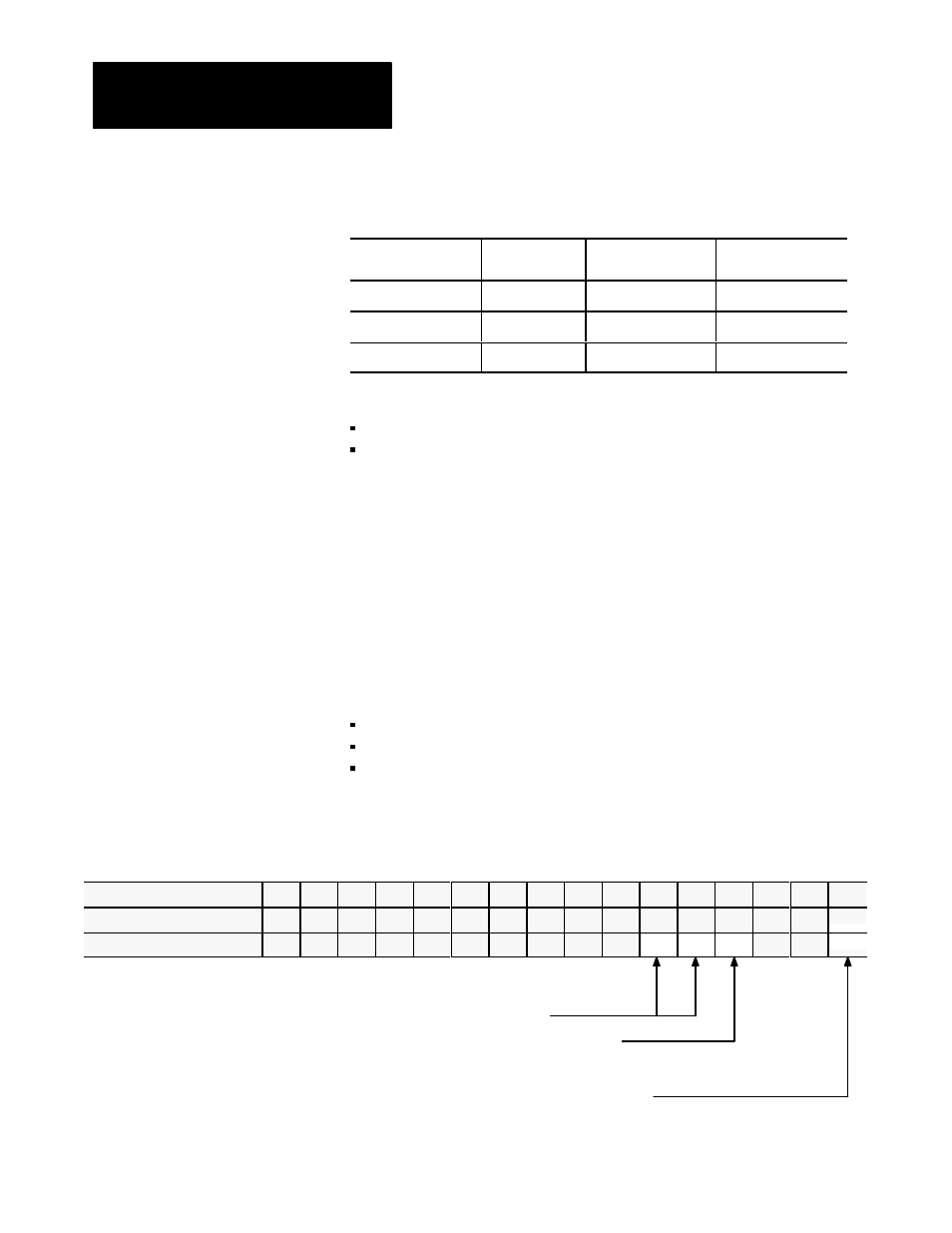
Worksheet 3ĆA
Select Module Parameters
Control Word MCC02ĆBxx
15
14 13 12
11
10
09 08 07 06 05 04 03 02 01 00
ProĆSet 600 Addr. B34/bit
543 542 541 540 539 538 537 536 535 534 533 532 531 530 529 528
Value
0
0
0
0
0
0
0
0
0
0
1
1
1
0
0
Example: If you select Inject, Clamp, and Eject mode with English units:
MCC02 = 00000000 00111000
Select Module Parameters
and I/O Ranges