Rockwell Automation 1771-QDC, D17716.5.93(Passport) PLASTIC MOLDING MODULE User Manual
Page 125
Load Initial Profile Setpoints
Chapter 8
8-8
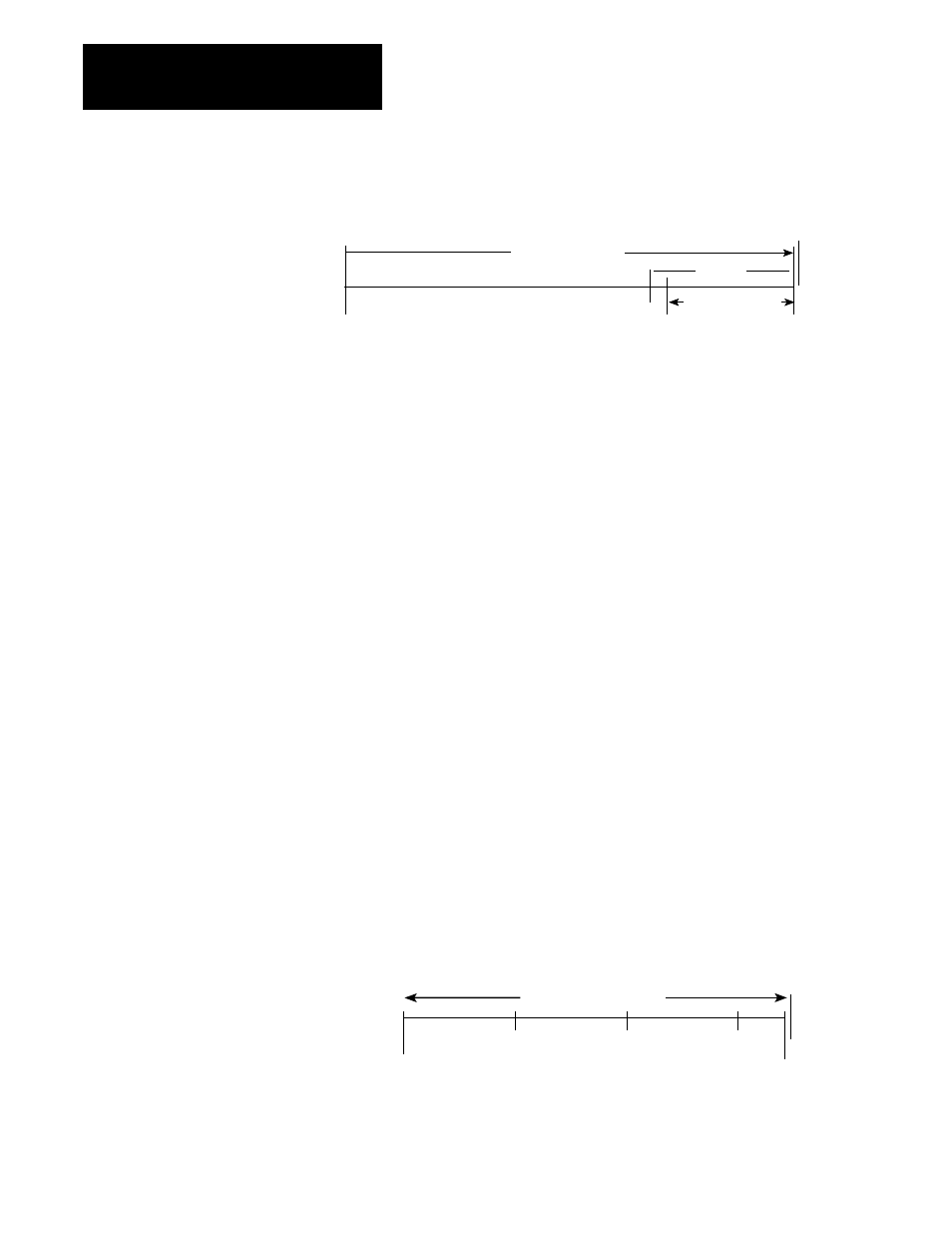
Figure 1.1
Example Setpoints for Mold Safe (CPC62) and Start Protection Zone (CPC61)
(OPC62)
Fully Open Mold Safe
Clamp Motion
zero
(CPC61) (CPC62)
LPC
Protection Zone
We recommend an initial value larger than the start LPC position you
would typically use during normal machine operation.
Record a value for CPC61 that is a safe distance from mold safe (CPC62)
on Worksheet 8-A.
The valve spanning procedures in chapter 9 require this initial value. We
help you select the correct final values for your application in chapter 10.
For additional information, refer to Section 3 of the Plastic Molding
Module Reference Manual (publication 1771-6.5.88).
EndĆofĆsegment Position Setpoint
(CPC11, 14, 17, 20, 23, 26, 29, 32, 35, 38)
Configure only the first clamp close profile segments.
Determine end-of-segment position setpoints for first clamp close as
follows:
1. Jog the mold to its full open position and observe the value in SYS27
(N40:179).
2. Subtract the value you recorded for Start LPC Position Setpoint
(CPC61) from SYS27.
3. Divide this difference into three equal sections. The dividing line of
each section should be recorded for the end-of-segment position
setpoints for segments 1, 2, and 3.
Important: Measure end-of-segment positions from zero (mold safe).
Fully Open
FCC Seg 1
(CPC11)
Mold Safe
(CPC62)
FCC Seg 2
(CPC14)
FCC Seg 3
(CPC17)
(CPC61)
Clamp Travel Range
zero