Analog wiring, 1762-if2of2 input type selection – Rockwell Automation 1766-Lxxxx MicroLogix 1400 Programmable Controllers User Manual User Manual
Page 64
50
Rockwell Automation Publication 1766-UM001H-EN-P - May 2014
Chapter 3 Wire Your Controller
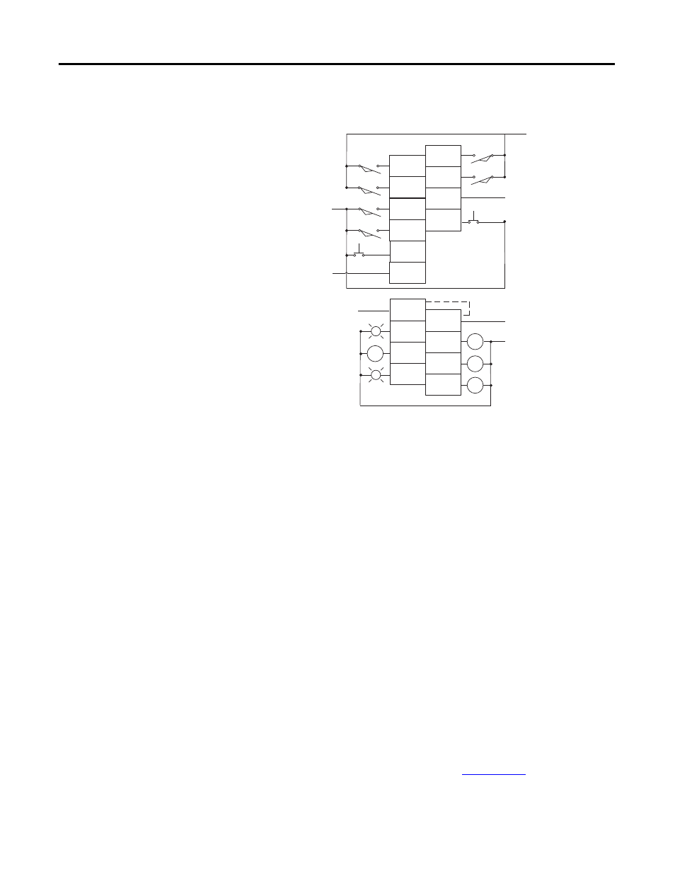
Figure 27 - 1762-IQ8OW6 Wiring Diagram
Analog Wiring
Consider the following when wiring your analog modules:
• The analog common (COM) is not connected to earth ground inside the
module. All terminals are electrically isolated from the system.
• Channels are not isolated from each other.
• Use Belden 8761, or equivalent, shielded wire.
• Under normal conditions, the drain wire (shield) should be connected to
the metal mounting panel (earth ground). Keep the shield connection to
earth ground as short as possible.
• To ensure optimum accuracy for voltage type inputs, limit overall cable
impedance by keeping all analog cables as short as possible. Locate the I/O
system as close to your voltage type sensors or actuators as possible.
• The module does not provide loop power for analog inputs. Use a power
supply that matches the input transmitter specifications.
1762-IF2OF2 Input Type Selection
Select the input type, current or voltage, using the switches located on the
module’s circuit board
and the input type/range selection bits in the
Configuration Data File. Refer to MicroLogix
1400 Programmable Controllers
Instruction Set Reference Manual, publicat
ou can access the
switches through the ventilation slots on the top of the module. Switch 1 controls
IN 6
IN 4
IN 3
IN 1
IN 5
IN 2
IN 0
OUT 4
OUT 2
OUT 0
VAC
VDC
VAC
VDC
DC
COM 1
OUT 3
OUT 1
IN 7
L1 or +DC
L1 or +DC
-DC (Sinking)
+DC (Sourcing)
Connected Internally
+DC (Sinking)
-DC (Sourcing)
L2 or -DC
OUT 5
+DC (Sinking)
-DC (Sourcing)
-DC (Sinking)
+DC (Sourcing)
DC
COM 0
CR
CR
CR
CR
44579