Advanced setup, Minimum freq, Maximum freq – Rockwell Automation 1336F PLUS II User Manual - Firmware 1.xxx-6.xxx User Manual
Page 94: Pwm frequency, Accel time 2, Decel time 2, Synchronized speed change function
6–12
Programming
Advanced
Setup
This group contains parameters that are required to setup advanced functions of the drive
for complex applications.
[Minimum Freq]
This parameter sets the lowest frequency the drive will
output.
Parameter Number
16
Parameter Type
Read and Write
Display Units / Drive Units
1 Hertz / Hertz x 10
Factory Default
0 Hz
Minimum Value
0 Hz
Maximum Value
120 Hz
[Maximum Freq]
This parameter sets the highest frequency the drive will
output.
This parameter cannot be changed while the drive is running.
Parameter Number
19
Parameter Type
Read and Write
Display Units / Drive Units
1 Hertz / Hertz x 10
Factory Default
60 Hz
Minimum Value
10 Hz
Maximum Value
400 Hz
[PWM Frequency]
This parameter sets the carrier frequency for the sine cod-
ed PWM output waveform.
This parameter cannot be changed while the drive is running.
Refer to the Derating Guidelines in Appendix A.
Parameter Number
45
Parameter Type
Read and Write
Display Units / Drive Units
2 KHz / KHz/2
Factory Default
2 KHz
Minimum Value
2 KHz
Maximum Value
A & B Frame Drives = 8 kHz
C Frame Drives & Up = 6 kHz
[Accel Time 2]
This value determines the time it will take the drive to ramp
from 0 Hz to [Maximum Freq]. The rate determined by this
value and [Maximum Freq] is linear unless [S Curve En-
able] is “Enabled.” It applies to any increase in command
frequency unless [Accel Time 1] is selected.
Parameter Number
30
Parameter Type
Read and Write
Display Units / Drive Units
0.1 Second / Seconds x 10
Factory Default
10.0 Sec
Minimum Value
0.0 Sec
Maximum Value
3600.0 Sec
[Decel Time 2]
This value determines the time it will take the drive to ramp
from [Maximum Freq] to 0 Hz. The rate determined by this
value and [Maximum Freq] is linear unless [S Curve En-
able] is “Enabled.” It applies to any decrease in command
frequency unless [Decel Time 1] is selected.
Parameter Number
31
Parameter Type
Read and Write
Display Units / Drive Units
0.1 Second / Seconds x 10
Factory Default
10.0 Sec
Minimum Value
0.0 Sec
Maximum Value
3600.0 Sec
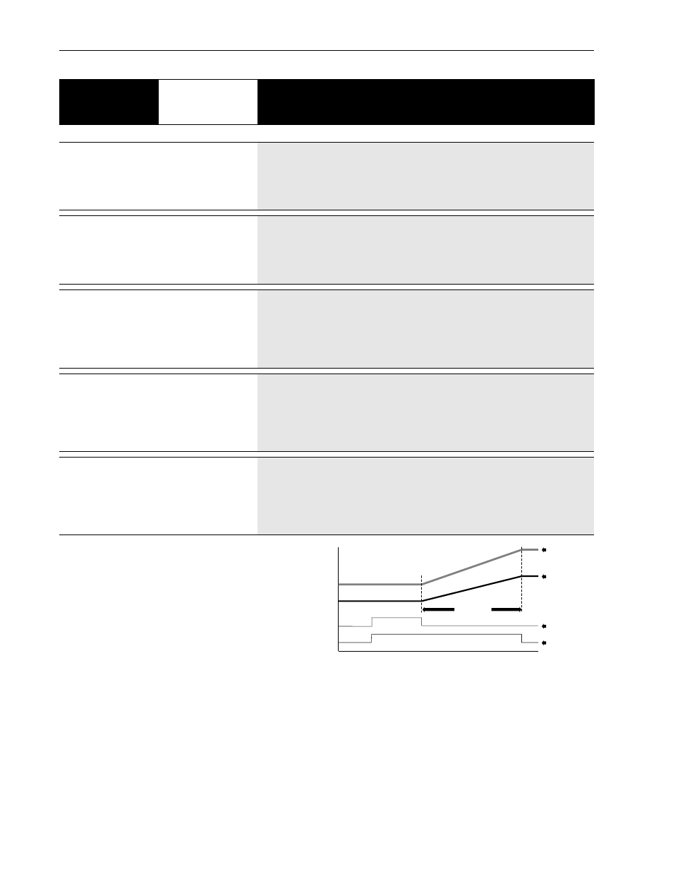
Time
Speed
New Drive #1
Reference
New Drive #2
Reference
Drive #1 & #2
Sync In
Change Ref's
[Sync Time]
[Application Sts]
Speed Sync Bit
Important: The accel/decel/s-curve control is active during speed sync and will limit the rate of change of
frequency if set “slower.”
Synchronized Speed Change Function
This function is typically used in an application where multiple drives, drive
different functions on one machine and the line speed must be changed.
To initiate the speed sync function:
- The drive must be running.
- [Sync Time] must be set to a non-zero value.
- [Freq Source] must be set to “Adapter 1-6” or “Preset 1-7.”
- A SYNC input must be energized.
The SYNC input can come from any of the programmable input terminals.
Example: [TB3 Term 22 Sel] = “Sync”
Important: Do not select more than one input terminal as the SYNC input.
The sync input can also come through SCANport from one of the communication options,
either as a “Type 1” or “Type 2” message. For further information, refer to the instructions supplied with the option. Also, see the section titled “Communications
Data Information Format” in Appendix A.
The usual sequence of events:
- Energize the SYNC input.
- The “Speed Sync” bit in [Application Sts] is set to “1”.
- The drive “holds” the last frequency reference value.
- The frequency command is changed and/or a different source is selected.
- De-energize the SYNC input.
- The drive will linearly ramp from the “held” reference to the new reference in a time set by [Sync Time].
- The “Speed Sync” bit in [Application Sts] is set to “0”.