Figure c.5 – Rockwell Automation 1336F PLUS II User Manual - Firmware 1.xxx-6.xxx User Manual
Page 202
C–6
CE Conformity
Filter Mounting
(continued)
1
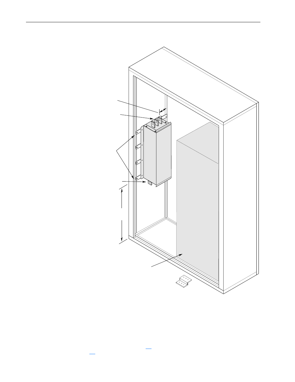
Input power (source to filter) and output power (filter to drive and drive to motor) wiring must be in conduit or have shielding/armor with equivalent attenuation. Shielding/
armor must be bonded to the metal bottom plate. See requirements 5 & 6 on page
2
Refer to the Filter Selection table on page
for frame references and corresponding catalog numbers.
75.0
(2.95)
Mounting Brackets
Typical Drive Placement
to Drive Input
Terminals
AC Input Terminals
Typical Bracket
for Stability
(G Frame Only - Mount between PE Terminals & Enclosure)
831.0
(32.72)
All Dimensions in Millimeters and (Inches)
Figure C.5
1336
PLUS
II
(Typical Filter Mounting)
Frames F & G
1, 2
Important: This information represents the
method used to mount 1336-RFB-475, 590 &
670 filters in an Allen-Bradley supplied EMC
enclosure. User supplied EMC enclosures must
follow all of the guidelines shown. Illustrations are
only intended to identify structural mounting
points and hardware shapes. You must design
and fabricate steel components based on the
actual mounting configuration, calculated loads
and enclosure specifications.
Important: Cooling fans are required for proper
drive operation. Fans and air intake openings
must be EMI shielded. Refer Appendix A for
CFM recommendations.
Important: A positive electrical bond must be maintained
between the enclosure and filter (including brackets), fans,
and drive. To assure a positive electrical bond, any paint
near all mounting points must be removed.