Auxiliary output - tb9, Control interface board installation and removal, Figure 2.7 jumper locations – Rockwell Automation 1336F PLUS II User Manual - Firmware 1.xxx-6.xxx User Manual
Page 50: Frames, A1 - a4 frames, B - g
2–40
Installation/Wiring
Auxiliary Output - TB9
The 480V or 600V (depending on the input voltage to the drive)
output terminal block (TB9) is only available on F Frame Drives. This
terminal block provides a three-phase, high voltage connection from
the load side of the AC input line fuses. Normally this connection is
used to power an external control transformer (user supplied) or other
auxiliary circuit. Refer to
for location.
Important:
Depending on the circuitry connected, additional fusing
may be required.
The auxiliary circuit can be utilized to a maximum current capacity of
8 amperes RMS.
The maximum and minimum wire size accepted by TB9 is 4.0 and 0.8
mm
2
(12 and 18 AWG). Use Copper wire Only with a minimum tem-
perature rating of 75 degrees C. Do not reduce wire gauge when using
higher temperature wire. Maximum torque is 0.90-1.81
N-m (8-16 lb.-in.).
Control Interface Board
Installation and Removal
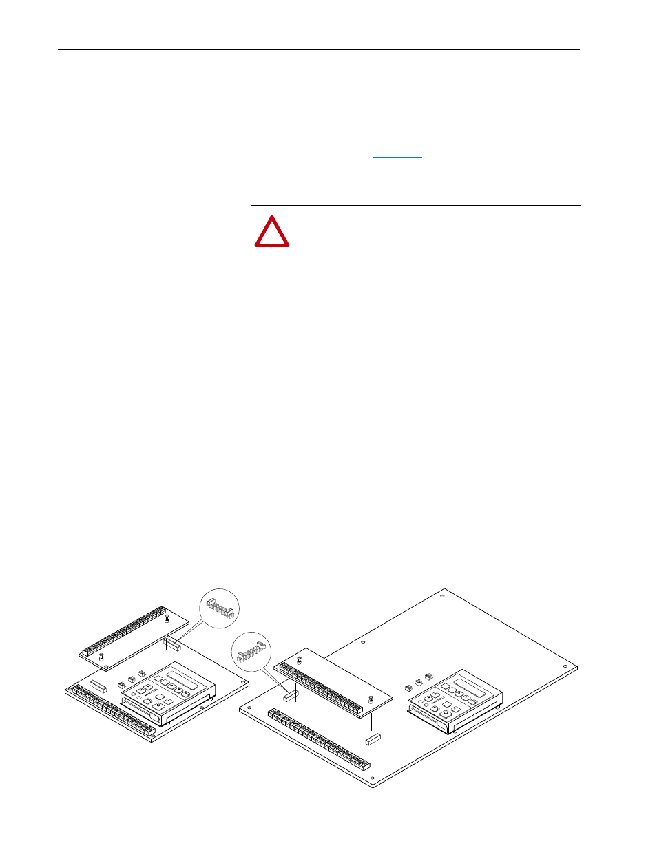
Important:
If the Control Interface Board is being installed, Main
Control Board jumpers at pins 3 & 4 and 17 & 18 of J2
must be removed and the proper [Input Mode] selected.
If this board is removed, these jumpers must be reinstalled
and the [Input Mode] parameter must be programmed to
“Status (1).”
Figure 2.7
Jumper Locations
!
ATTENTION: The installation of auxiliary circuits must
comply with the national codes and standards (NEC, VDE,
BSA, etc.) and local codes regarding wire type, conductor
sizes, branch circuit protection and disconnect devices. Fail-
ure to do so may result in personal injury and/or equipment
damage.
J2
J2
Frames
1
A1 - A4
Frames
1
B - G
1
Refer to page 1–1 for frame reference classifications.
JO
G
ES
C
SE
L
JO
G
ES
C
SE
L
J11
J8
J13
J11
J8
J13