Standard analog i/o setup, Standard analog i/o setup –33, The 1336 – Rockwell Automation 1336F PLUS II User Manual - Firmware 1.xxx-6.xxx User Manual
Page 43: Remote potentiometer examples, Plus
Installation/Wiring
2–33
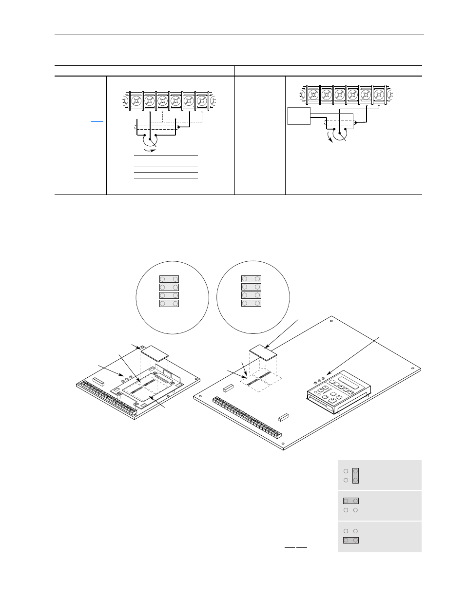
Remote Potentiometer Examples
Standard Analog I/O Setup
The 1336
PLUS
II
has a series of jumpers to connect the standard I/O
to TB2 when no analog options (LA1, LA2, etc.) are present. Connec-
tors J9 and J10 (see below) each have four jumpers connecting pins
1-2, 3-4, 5-6 and 7-8. These jumpers must be in place for the inputs
and outputs to be active at TB2.
In addition, each input can be configured
for 0-10V, 0-20 mA or potentiometer.
Placing a jumper across the top of the con-
nector (J8, J11, J13) configures that input
for 0-10V operation. The bottom provides
0-20 mA and the right-side provides
potentiometer operation. Please note that
all three are factory set at 0-10V.
Important:
Inputs 0, 1 & 2 are not located
in logical order on the board.
to Standard I/O
with Optional I/O
10k Ohm Remote
Potentiometer to
Standard Analog
Input
Refer to page
for Analog I/O
specifications
10k Ohm Remote
Potentiometer
when LA2, LA6 or
LA7 Option Board
is Installed
1
5V Ref.
Common
Signal
Common
See table below for further jumper info.
2
3
4
5
6
TB2
Terminal
2
3
6
Input
0
1
2
Jumper . . .
(Set
to "Pot")
J8
J13
J11
Input 0 Shown - See Table below for other Inputs
1
1
User
Supplied
5V
Common
Signal
Common
Jumper J11 must be set to "Pot."
2
3
4
5
6
2
1
If an Option Board is installed in Slot A, the +5V pot. reference
will not be available at terminal 1. If a 5V source is required, it
must be user supplied.
2
Input to Terminal 6 is only valid for standard I/O or with an LA1
option installed. If an LA1 option is installed, Standard Analog
Input 2 is maintained at this terminal – configure with J11. A pot
cannot be connected to an isolated input.
Frames
1
A1 - A4
Frames
1
B - G
1
Refer to page 1–1 for frame reference classifications.
JO
G
ESC
SEL
ANALOG I/O
SLO
T B
8
6
4
2
7
5
3
1
J10
ANALOG I/O
SLO
T A
8
6
4
2
7
5
3
1
J9
Connector J9
Connector J10
J8, J11, J13
TB2-4
Common
TB2-3
Input 1
TB2-2
Input 0
TB2-1
Pot Ref. (5V)
TB2-9
Common
TB2-8
Output 1
TB2-7
Output 0
TB2-6
Input 2
Text Does Not Appear on Board
(for explanation purposes only)
Remaining Pins
Not Shown
Text Does Not Appear on Board
(for explanation purposes only)
Remaining Pins
Not Shown
Analog Option Board
(Slot A)
ANALOG I/O
SLO
T B
8
6
4
2
7
5
3
1
J10
ANALOG I/O
SLO
T A
8
6
7
5
3
1
J9
Analog Option Board
(Slot A)
J9, J10
J9, J10
Slot B
Slot B
J8, J11, J13
0-10V
J13 (TB2-3, Input 1)
(Pot Configuration Shown)
0-20 mA
Po
t
P
ot
Po
t
0-10V
J8 (TB2-2, Input 0)
(0-10V Configuration Shown)
0-20 mA
0-10V
J11 (TB2-6, Input 2)
(0-20 mA Configuration Shown)
0-20 mA