Analog i/o, Analog i/o –32, The 1336 – Rockwell Automation 1336F PLUS II User Manual - Firmware 1.xxx-6.xxx User Manual
Page 42: Plus
2–32
Installation/Wiring
Analog I/O
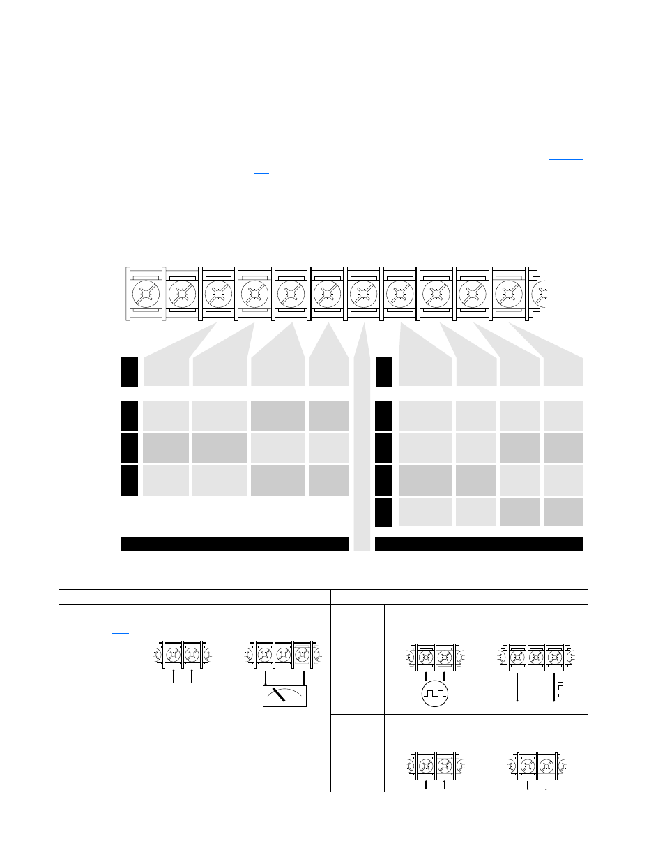
The 1336
PLUS
II
analog I/O configuration provides a standard set of
inputs and outputs with the capability to install up to 2 option boards,
thus replacing the standard I/O with a variety of options. All connec-
tions are performed at TB2. Installing an option board in the slot A or
B location will change the function of those terminals on TB2 from
standard. Only one option board can be installed in each slot.
shows the standard and optional I/O configurations.
Figure 2.6
Analog I/O – TB2
Analog 0-10V, 4-20 mA and Pulse I/O Examples
1
TE
TE
Signal
Common
Only Present
on B Frame
& Up Drives
2
3
4
5
6
9
8
7
Isolated
Input 0 (–)
10V or 20mA
Isolated
Input 0 (–)
±10V, ±20mA
Isolated
Input 0 (–)
±10V, ±20mA
Isolated
Input 0 (+)
10V or 20mA
Isolated
Input 0 (+)
±10V, ±20mA
Isolated
Input 0 (+)
±10V, ±20mA
LA2
LA6
LA7
Analog I/O Option Slot A
Analog I/O Option Slot B
Isolated
Input 1 (+)
10V or 20mA
Thermistor
Isolated
Input (+)
Isolated
Input 1 (+)
10V or 20mA
Isolated
Input 1 (–)
10V or 20mA
Thermistor
Isolated
Input (–)
Isolated
Input 1 (–)
10V or 20mA
Pot.
Reference
+5V
1, 3
Single-Ended
Input 0
Pot., 10V or 20mA
Single-Ended
Input 1
Pot., 10V or 20mA
Signal
Common
S
i
g
n
a
l
C
o
m
m
o
n
Std.
LA1
LA3
LA4
LA5
Std.
or (select 1)
or (select 1)
Single-Ended
Input 2
2
Pot., 10V or 20mA
Isolated
Output 0 (+)
10V or 20mA
Isolated
Input 2 (+)
10V or 20mA
Single-Ended
Output 0
10V or 20mA
Single-Ended
Output 0
10V or 20mA
Isolated
Output 0 (–)
10V or 20mA
Isolated
Input 2 (–)
10V or 20mA
Non-Isolated
250 kHz
Pulse Output
Single-Ended
Output 1
20mA Only
Isolated
Output 1 (+)
10V or 20mA
Isolated
Output 1 (+)
10V or 20mA
Isolated
250 kHz
Pulse In (+)
0-20mA
Output
Return
Isolated
Output 1 (–)
10V or 20mA
Isolated
Output 1 (–)
10V or 20mA
Isolated
250 kHz
Pulse In (–)
Signal
Common
Single Ended
Output 1
0-10V Only
Single Ended
Output 0
0-10V Only
Single-Ended
Input 2
Pot., 10V or 20mA
1
If an Option Board is installed in Slot A, the +5V pot. reference will not be
available. If a 5V source is required, it must be user supplied.
2
Standard Analog Input 2 is maintained at this terminal – configure with J11.
3
10k Ohm potentiometer required.
Standard I/O
Optional I/O
Standard Analog
Refer to page
for Analog I/O
specifications
Pulse with
LA5 Option
Analog I/O
with LA2/LA3
Options
0-10V
Standard Analog Input 2
(Non-Isolated)
Standard Analog Output 0
(0-10V Non-Isolated)
5
6
9
8
7
+
+
–
–
Jumper J11 Set to "0-10V"
5
6
7
Isolated Pulse Train Input
to LA5 Option Board
Pulse Train Output from LA5
Option Board (Non-Isolated)
Common
+
–
9
8
Pulse
Source
Isolated Input to
LA2 Option Board
Isolated Output from
LA3 Option Board
+
–
2
1
+
–
9
8