W and, Figure 6.1, Sl0 logic step – Rockwell Automation 1336F PLUS II User Manual - Firmware 1.xxx-6.xxx User Manual
Page 144: Sl1 logic step, Sl2 logic step, Sl3 logic step, Sl4 logic step, Sl5 logic step, Sl6 logic step, Step logic
6–62
Programming
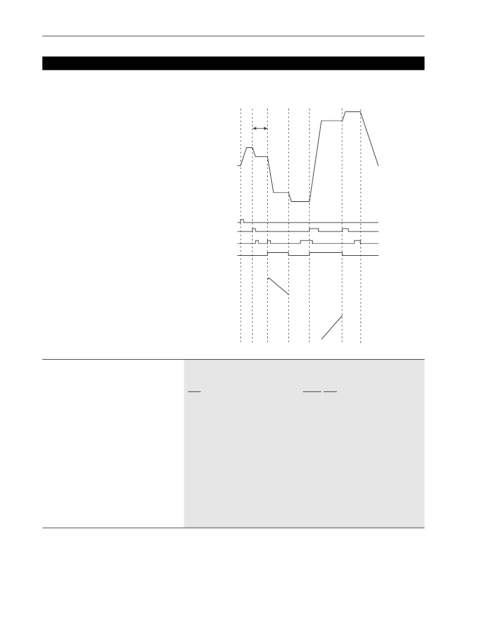
Figure 6.1
Step Logic
Step Logic
0
1
3
4
5
6
End
10 Sec
60Hz
50Hz
40Hz
30Hz
20Hz
10Hz
0Hz
-10Hz
-20Hz
-30Hz
-40Hz
-50Hz
SL Input 1
SL Input 2
Step Logic Output
-15
10
5
0
-5
-10
15
0
20
15
10
5
Start
Encoder Counts
Since Start
of Step
Pulse Counts
Since Start
of Step
[SL0 Logic Step]
– Firmware 5.001 & later
[SL1 Logic Step]
[SL2 Logic Step]
[SL3 Logic Step]
[SL4 Logic Step]
[SL5 Logic Step]
[SL6 Logic Step]
When the logic in this parameter is true, the program will
move to the next step. The SL1 and SL2 inputs are desig-
nated in [TB3 Term xx Sel].
The logic which refers to time is also for encoder or pulse
counts. Time can be replaced with counts when using the
encoder and pulse inputs.
When using “Time and SLx” or “Time not SLx” the time or
counts need to elapse before the logic input will be
checked.
Parameter Number 335, 341, 347, 353, 359, 365, 371
Parameter Type
Read and Write
Factory Default
“Step On Time”
Units
Display Drive
“Skip Step” 0
“Step On Time” 1
“SL1 In True” 2
“SL2 In True” 3
“SL1 In False” 4
“SL2 In False” 5
“Any SL True” 6
“All SL True” 7
“No SL True” 8
“SL1 not SL2” 9
“SL2 not SL1” 10
“Time and SL1” 11
“Time and SL2” 12
“Time not SL1” 13
“Time not SL2” 14
“Do Not Step” 15