Chapter 2, Installation/wiring, Mounting – Rockwell Automation 1336F PLUS II User Manual - Firmware 1.xxx-6.xxx User Manual
Page 11: Mounting –1, Chapter
Chapter
2
Installation/Wiring
Chapter 2 provides the information you need to properly mount
and wire the 1336
PLUS
II
Drive. Since most start-up difficulties
are the result of incorrect wiring, every precaution must be taken
to assure that the wiring is done as instructed. All items must be
read and understood before the actual installation begins.
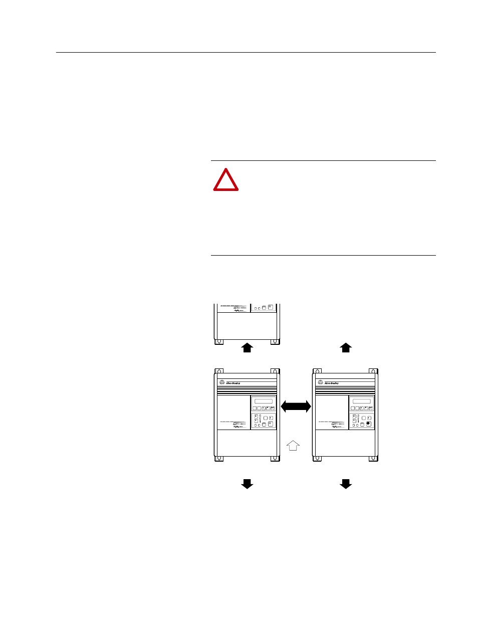
Mounting
Minimum Mounting Requirements for Proper Heat Dissipation
(Dimensions shown are between drives or other devices)
!
ATTENTION: The following information is merely a
guide for proper installation. The Allen-Bradley
Company cannot assume responsibility for the
compliance or the noncompliance to any code, national,
local or otherwise for the proper installation of this drive
or associated equipment. A hazard of personal injury
and/or equipment damage exists if codes are ignored
during installation.
JOG
ESC
SEL
101.6 mm
(4.0 in.)
JOG
ESC
152.4 mm
(6.0 in.)
152.4 mm
(6.0 in.)
152.4 mm
(6.0 in.)
152.4 mm
(6.0 in.)
UP
Important:
A4 Frame drives should not be mounted on a combustible surface. However,
if the drive must be mounted on a combustible surface, 6.35 mm (0.25 in.)
spacers must be provided under the mounting feet of the drive.
F Frame drives require a minimum of 152.4 mm (6.0 in.) between the drive back
and mounting wall, if drives are mounted with sides touching another device or wall.
A minimum of 76.2 mm (3.0 in.) is required on the sides if the back of the drive is
mounted against a wall or other device.