Step 20 – Rockwell Automation 1336F PLUS II User Manual - Firmware 1.xxx-6.xxx User Manual
Page 80
5–12
Start-Up
Remove ALL Power
Disconnect Load
Apply Power to Drive
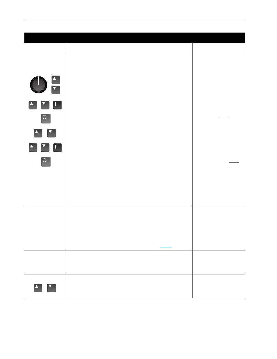
17. Optimum tuning requires motor rotation and can be achieved by running the
drive/motor under a “no-load” condition.
A. Remove all power to the drive. Disconnect the load from the system by
decoupling the motor shaft. Reapply drive power.
B. While monitoring [Freq Command] in the Metering group, adjust the speed
source for the drive (digital, analog pot, etc.) to 3/4 base speed.
C. Press the Increment/Decrement keys until “Flux Current” is displayed. Start
the drive and record this value.
D. Stop the drive.
E. Press the Increment/Decrement keys to display “Freq Command.” Adjust
the speed source for the drive to zero Hz.
F.
Press the Increment (or Decrement) key to display “Output Voltage.” Start
the drive and record the value.
G. Stop the drive.
H. Program the values recorded above into the following parameters.
[Flux Amps Ref] = [Flux Current] at 45 Hz.
[IR Drop Volts] = [Output Voltage] at zero Hz.
Important: Some motors (i.e. 6 pole, special, etc.) may be particularly sensi-
tive to the adjustment of [IR Drop Volts]. If this tuning procedure does not give
the desired performance, adjust [IR Drop Volts] up/down, 1 or 2 volts until
desired response is achieved.
Freq Command
xx Hz
Flux Current
1 Amp
Flux Current= Amps
Freq Command
0 Hz
Output Voltage
0 Vlts
Output Volts at 0 Hz = V
Adjusting Flux Up Time
18. On larger motors (37 kW/50 HP, typical) additional acceleration performance
can be gained by adjusting [Flux Up Time]. This parameter determines the
amount of time that the drive will inject current at [Current Limit] levels before
acceleration begins. This pre-acceleration time builds flux in the motor to allow
for optimum acceleration, and may result in shorter overall acceleration. If
better performance is required, adjust [Flux Up Time]. Begin with 0.2 seconds
(default is zero) and increase as necessary.
For the typical steps involved when programming, refer to
.
Tuning Slip Comp Gain
19. To adjust the recovery response to load changes [Slip Comp Gain] can be
increased. However, increasing the gain value too high may cause system
instability. The factory default value is set to minimum. Fine adjustment will
require operation with a load.
Slip Comp Gain
1
Set Power-Up Display
20. With HIM software versions 2.02 & up, the power-up display (Status, Process
or Password) can be programmed to appear when drive power is applied.
Simply access the desired display and simultaneously press the Increment
and Decrement keys.
Advanced Start-Up Procedure
Press these keys . . .
while following these steps . . .
The HIM Display will show . . .
or
or
or
&
or
&
or