Options, Figure 4.14 programming terminal – Rockwell Automation 1395 Digital DC Drive FRN 5-10.10/9.30 User Manual
Page 82
Chapter 4
Hardware Description
125 – 300 HP, 230VAC 250 – 600 HP, 460VAC
4-18
Options
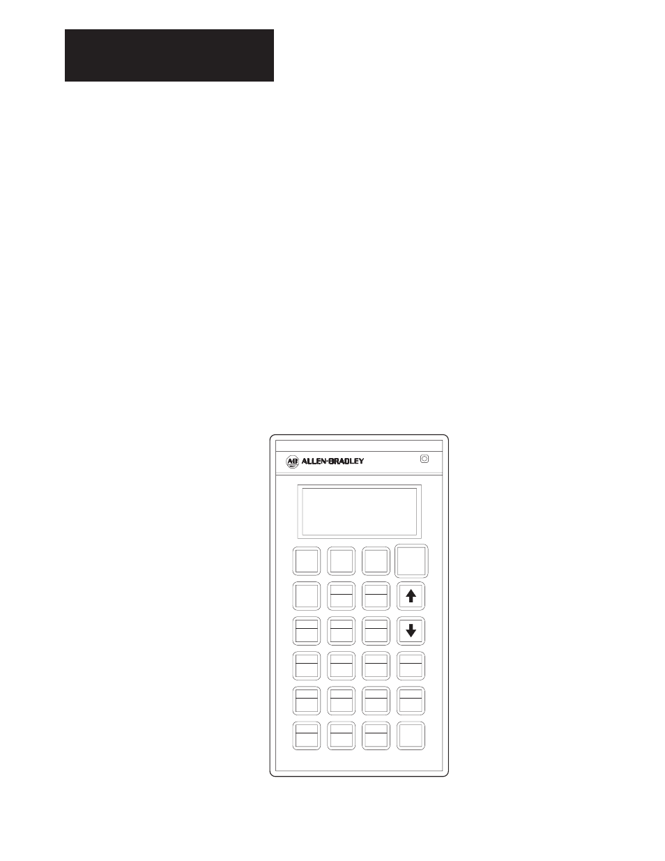
Programming Terminal Interface – Both versions of the handheld
Programming Terminal are used to access information in the firmware of
the 1395. Keypads on both the handheld programming terminal and the
door-mounted terminal (shown in Figure 4.14) can be used to perform the
following functions:
•
Monitor real time parameter values
•
Change parameter values
•
Start/Stop the drive (depending on Model of Programming Terminal)
•
Sets drive configuration
•
Backup parameter values to EEPROM
•
Monitor fault information
Interface between the 1395 Main Control Board and the handheld
Programming Terminal is accomplished using a 9 pin type connector
physically mounted on the end of TB3. The cable coming from the D shell
connector is connected to J4 on the Main Control Board. For a detailed
description of the Programming Terminal, refer to the Programming
Terminal Installation and Operation Manual.
Figure 4.14
Programming Terminal
AB0446A
LOCAL
PROGRAMMING TERMINAL
START
JOG
1
JOG
2
STOP
ALT
LOCAL
DEC
REMOTE
INC
PRE 4
7
PRE 5
8
X REF
9
PRE 1
4
PRE 2
5
PRE 3
6
HOME
MENU
D
1
E
2
F
3
BASE
DEL
A
0
B
.
C
+/–
ENTER
Note: The Programming Terminal can be hand-held or door-mounted when used with the
mounting kit.