Rockwell Automation 1395 Digital DC Drive FRN 5-10.10/9.30 User Manual
Page 79
Chapter 4
Hardware Description
125 – 300 HP, 230VAC 250 – 600 HP, 460VAC
4-15
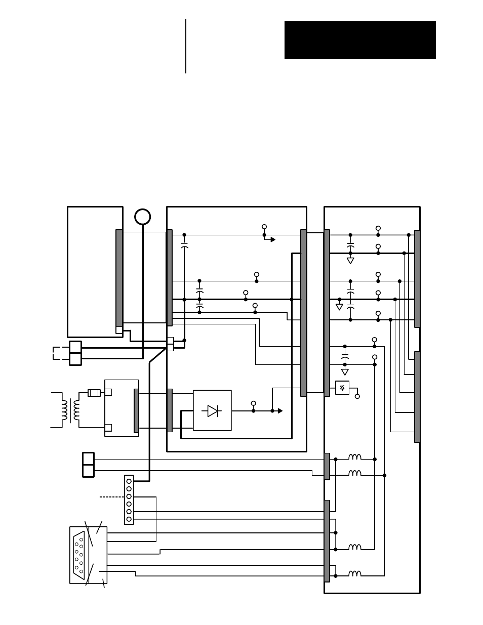
DC Control Voltage Distribution – The Unit Power Supply converts
115VAC (supplied as shown in Figure 4.12) to +5VDC and +/– 12VDC
control voltages. In addition to the voltages supplied by the Unit Power
Supply, the Power Stage Interface converts the 20VAC coming from the
control transformer PT to 24VDC which is used for relay logic and
provides the supply voltage to the SCR Pulse Transformer and Snubber
boards to produce SCR gate signals for the armature and field.
Figure 4.12
DC Power Distribution and Control Common
J6
Port
B
J5
115
VAC
3
4
TB1
J2
20
VAC
FEEDBACK
BOARD
J1
A6
UNIT POWER
SUPPLY
J7
TP51 +5VDC
J7
TP52 DGND
5
J2
TP55 +12VDC
TP57 AGND
TP56 –12VDC
Port
A
TP54 ISO 12V
TP53 ISO GND
J1
Balun
A7 POWER
STAGE
INTERFACE
TB3
13
14
Encoder
Power
Supply
(+12 VDC)
10
11
Balun
J4
TP4 +5VDC
+5V
J8
To
Prog
Term
1
3
5
7
9
2
4
6
8
TE
TB10
1
2
Common (ISO)
+12 VDC (ISO)
Common (ISO)
+12 VDC (ISO)
TP6 +24VDC
TP1 –12VDC
TP3 Common
TP5 +12VDC
ISO +12VDC
ISO RTN
PT
PE
TE
TB1
F5
TB5
Shield
TX +
RX +
TX –
RX –
PE
C11
C40
C39
10
10
9
9
Balun
Balun
TE
A8 MAIN
CONTROL
BOARD
TP41 24V Sense
(approx. 4VDC)
- 20P PowerFlex DC Drive - Frame D Bimetal Thermostat (10 pages)
- 1336S_F_T_E_R F Frame Snubber Resistor Repl. (6 pages)
- 22-COMM PowerFlex 4-Class DSI (Drive Serial Interface) Network Communication Adapter (4 pages)
- 8-545 Plug In Solid State Relay (2 pages)
- 20-HIM-B1 PowerFlex 7-Class HIM Bezel (DPI) (4 pages)
- 100 Contactors with DC Coil (1 page)
- 100 Contactors with DC Coil (2 pages)
- 20P PowerFlex DC Drive - Frame D Switching Power Supply Circuit Board (6 pages)
- 140G-MTFx_MTHx_MTIx_MTKx Trip Unit Installation-140G-M (6 pages)
- 45BRD Analog Laser Sensor (4 pages)
- 20D Multi-Device Interface Option Board for PowerFlex 700S Drives (20 pages)
- 56RF RFID 18 mm Cylindrical Transceiver (2 pages)
- 42KC Miniature Rectangular: 5V DC Version (2 pages)
- 20P PowerFlex DC Drive - Frame A Switching Power Supply Circuit Board (16 pages)
- 21P-MISC-A-TP-2 Transition Tube Kit #C19-6/7 For PowerFlex 755 w/OEM Liquid Cooling Fr 6/7 Drive (2 pages)
- 42BT Background Suppression Sensor (3 pages)
- 42CB High Speed 18mm Cylindrical (4 pages)
- 140EX-JE2_JE3 Molded Case Circuit Breaker (4 pages)
- 140G-K-EAM1A Early Make Aux Contact for Rotary Handle Oper Mech-140G-K (1 page)
- 140G-K-EAM1A Early Make Aux Contact for Rotary Handle Oper Mech-140G-K (3 pages)
- 20-HIM-A6 PowerFlex (Human Interface Module) (74 pages)
- 42CF General Purpose 12mm Cylindrical (4 pages)
- 20D PowerFlex 700S Phase II Drive Frames 1...6 (80 pages)
- 140EX-HE1_HE2 Molded Case Circuit Breaker (6 pages)
- 140EX-HE1_HE2 Molded Case Circuit Breaker (4 pages)
- 20B PowerFlex 700 Custom Firmware - Pump Off (12 pages)
- 20-WIM-N4S DPI Wireless Interface Module (92 pages)
- 140U H-Frame Circuit Breaker Fixed and Adjustable Thermal Trip (7 pages)
- 140U H-Frame Circuit Breaker Fixed and Adjustable Thermal Trip (2 pages)
- 60-2619, 42JS Swivel/Tilt Mounting Bracket (1 page)
- 22A PowerFlex 4/40/400 Flange Mount (4 pages)
- 45MLA Controller Installation Instructions (16 pages)
- 20P PowerFlex DC Drive - Cooling Fan for Frame A Drives Above 73A at 230V 460V AC (6 pages)
- 42JS Series 7000 to 42JS VisiSight Replacement Kit (2 pages)
- 22A PowerFlex 4-Class HIM Bezel (DSI) (4 pages)
- 42CS Stainless Steel Photoelectric Sensors (4 pages)
- 20L-LL PowerFlex 700L Liquid-to-Liquid Heat Exchanger (40 pages)
- 20P PowerFlex DC Drive - Frame B SCR Modules (20 pages)
- 22B PowerFlex 40 Quick Start FRN 5.xx - 6.xx (161 pages)
- 22B PowerFlex 40 Quick Start FRN 5.xx - 6.xx (22 pages)
- 22F PowerFlex 4M Input RFI Filters (2 pages)
- 45LFM Capacitive Label Sensor (4 pages)
- 140G-Rx Installation Instruction-140G-R (2 pages)
- 140G-Rx Installation Instruction-140G-R (29 pages)
- 22C PowerFlex 400 AC Drive Quick Start - FRN 1-4.xx (28 pages)