Rockwell Automation 1395 Digital DC Drive FRN 5-10.10/9.30 User Manual
Page 148
Chapter 6
Installation
6-24
The voltage used must be the same as the voltage supplied for the
motor thermostat input.
IMPORTANT: The 24VDC provided at TB3-11 and 12 must only be
used for the 24VDC ECOAST circuit.
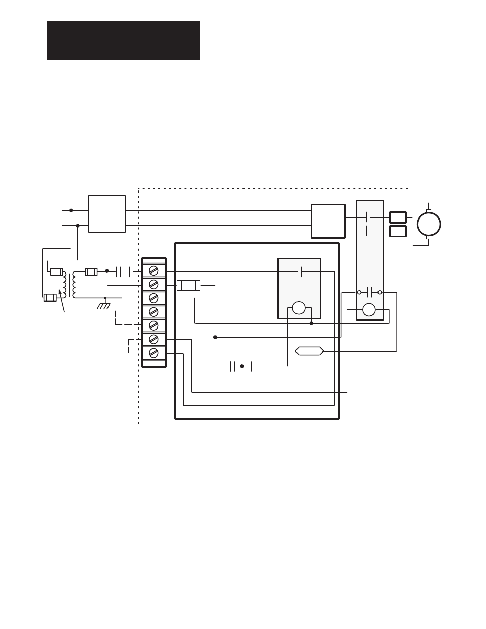
Figure 6.13
115VAC Input and Contactor Control Connections –
1 to 30 HP, 230VAC; 2–60HP, 460VAC
K3
K
M1
PR
M
A1
A2
A1
A2
Armature
Bridge
TB2
3
4
5
1
115V AC
Fuse
Optional
External
Control Con-
tacts
230 or
460VAC
F3
2
6
7
115 VAC
115 VAC Common
See Step
8
PSI/Switcher Board
1395
M1–X
CVERIFY
To ECOAST
Line
Reactor
or
Isolation
Transformer
L1
L2
L3
AC
Supply
TE
PE
5. Wire External drive Ready Indicator. Terminals TB3-7 and 8 provide
connection to the output contact of the Ready/Fault relay located on the
Power Stage Interface Board. The contacts are rated for 1A at 24VDC
or 0.6A at 115VAC.
6. Wire 115VAC Supply Voltage. It is recommended that the user ground
the 115V secondary of the transformer. The drive Does Not derive its
own control voltage. Therefore, 115VAC must be supplied to the drive
from an external source. A control transformer having a primary of
230V or 460V, based on the drive rating, and a secondary of 115V is
recommended. Primary and secondary must be fused to meet NEC
code. Fuse type FRN and FRS are recommended.
Terminal Connections and VA loads for the different ratings are
outlined in Table 6.N.