Rockwell Automation 1395 Digital DC Drive FRN 5-10.10/9.30 User Manual
Page 160
Chapter 6
Installation
6-36
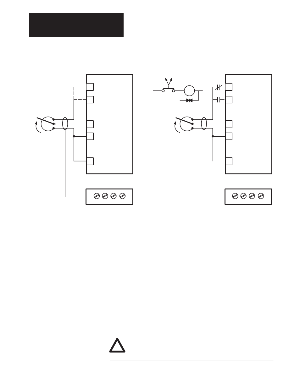
Figure 6.24
Typical Analog Input Connections
28
29
31
32
30
TB3
+10V DC P.S.
–10V DC P.S.
EXT. VELOCITY REF.
P.S. COMMON
Bi-directional Operation
(Requires Regen. Drive)
IMPORTANT: Connect
shield to drive end only.
Other end is to be insu-
lated and left floating.
Reference *
2.5k Ohm
Minimum
28
29
31
32
30
TB3
+10V DC P.S.
–10V DC P.S.
P.S. COMMON
Uni-directional Operation
Reference*
2.5k Ohm
Minimum
R
R
Forward
Reverse
R*
Reverse Relay
* External to the Drive
*
EXT. VELOCITY REF.
+
–
EXT. VELOCITY REF.
EXT. VELOCITY REF.
+
–
IMPORTANT: Connect
to either terminal 28 or
29, Not Both
TB4 (TB-10 on 125-600 HP)
TB4 (TB-10 on 125-600 HP)
Analog Input – Velocity and Trim Reference
Connections for the velocity and trim reference inputs can be for uni- or
bi-directional operation, using the internal drive
±
10VDC power supply
Tach Velocity – The Digital Reference Adapter Board is not
pre-configured for DC tachometer feedback. The user will have to
reconfigure the drive by replacing the Trim Velocity Reference (parameter
161) with the Tach Velocity (parameter 156).
The analog tachometer device generates a DC voltage that is direction
sensitive and proportional to speed. The tach output must be connected to
an analog input channel on the Discrete Adapter Board. Most industrial
tachs have an output greater than the
±
10V range of the analog inputs. The
tach output must be scaled down, by an external voltage divider network,
so that the entire speed range of the motor can be represented by a
±
9V
feedback signal.
ATTENTION: Connecting a tach which has an output range
greater than
±
10V directly to the analog input channel can
severely damage the adapter board.
!