Armature bridge components – Rockwell Automation 1395 Digital DC Drive FRN 5-10.10/9.30 User Manual
Page 25
Chapter 2
Hardware Description
1 – 30 HP, 230VAC 2 – 60 HP, 460VAC
2-3
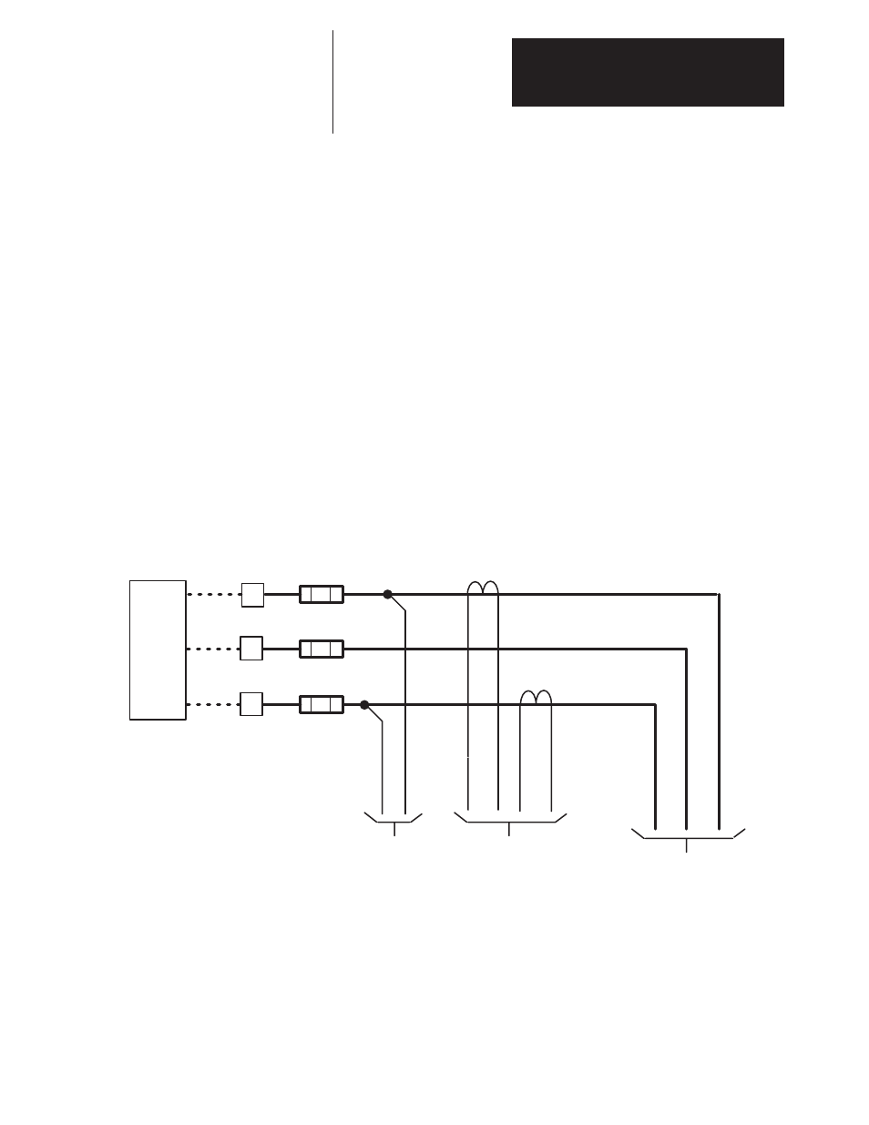
Armature Bridge Components
A general description of the components in the armature bridge (Figures
2.2 and 2.3) and their operation is detailed here:
AC Line Reactor – When connecting the drive directly to the main
distribution system an AC line reactor must be used to protect the power
bridge from rapid rate of current changes (di/dt).
When an isolation transformer matched to the unit rating is used, an AC
line reactor is not required.
Fast acting semiconductor fuses F1, F2 and F3 are standard on all drives.
Synchronization – The three-phase input to the drive is fed directly to the
Power Board. The Power Board scales down the voltage and develops the
synchronization information to be used by the Main Control Board.
AC Current Feedback – Current Transformers ACT-1 and ACT-2
(Figure 2.2) are used to provide current feedback information to the
PSI/Switcher Board. The PSI/Switcher Board rectifies the feedback and
scales a DC voltage representing the current feedback. This signal is then
sent to the Main Control Board.
Figure 2.2
Armature Bridge Components (INPUT)
To TB1
Power Board
Field Bridge
ACT-1
F1
F2
F3
Isolation
Transformer
or
Line
Reactor
ЗЗЗЗ
ЗЗЗЗ
ЗЗЗЗ
ЗЗЗЗ
ЗЗЗЗ
ЗЗЗЗ
ЗЗЗЗ
ЗЗЗЗ
L1
L2
L3
To PSI/Switcher
Board
ACT-2
To Power Board