Rockwell Automation 1395 Digital DC Drive FRN 5-10.10/9.30 User Manual
Page 131
Chapter 6
Installation
6-7
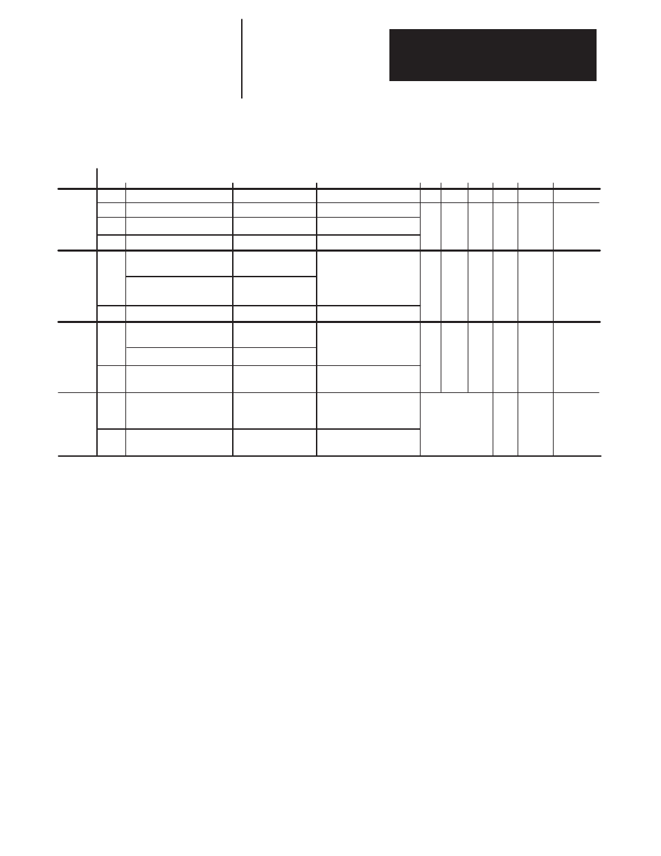
Table 6.B
Cable and Wiring Recommendations
Category
Power
Control
Signal
(Process)
Signal
(Comm)
Wiring
Class
1
2
3
4
5
Signal Definition
AC Power (600V or greater)
AC Power (less than 600V)
DC Power
DC Power
115VAC/DC Logic
115VAC Power
24VAC/DC Logic
Analog Signals,
DC Supplies
Digital (low speed)
Digital
(high speed)
Serial
Communication
Serial Communication
(greater than 20k baud)
Signal Examples
2.3kV 3/Ph AC Lines
460V 3/Ph AC Lines
DC Motor Armature
Reg.DC Motor Field
Relay Logic/PLC I/O
Motor Thermostat
Power Supplies,
Instruments
PLC I/O
Reference/Feedback
Signal, 5 to 24VDC
TTL
I/O, Encoder, Counte
Pulse Tach
RS-232, 422 to
Terminals/Printers
PLC Remote I/O,
PLC Data Highway
Cable Type
per NEC & Local Codes
per NEC & Local Codes
per NEC & Local Codes
per NEC & Local Codes
per NEC & Local Codes
per NEC & Local Codes
Shielded Cable – Belden
8735, 8737, 8404
Shielded Cable – Belden
9728, 9730
Shielded Cable – Belden
RS-232 – 8735, 8737
RS-422 – 9729, 9730
Twinaxial Cable – Belden
9463, A-B 1770-CD
1
0
3/9
3/9
3/
18
2/3/4
3/9
0
3/6
3/
12
5/6
3/9
3/6
0
3/9
7/8
3/18
3/12
3/9
0
9/10/11
Note6
Note 6
Note 6
1/3
Spacing
Notes
1/2/5
1/2/5
1/2/5
Minimum Spacing in Inches between Classes –
Steel Conduit/Tray
Example:
Spacing relationship between 480VAC incoming power leads and 24VDC logic leads.
– 480VAC leads are Class 2 ; 24VDC leads are Class 6
– For separate steel conduits, the conduits must be 3 inches (76 mm) apart
– In a cable tray, the two groups of leads are to be 6 inches (152 mm) apart
Spacing Notes:
1. Both outgoing and return current carrying conductors are to be pulled in same
conduit or laid adjacent in tray.
2.
Cables of the following classes can be grouped together.
A.
Class 1; Equal to or above 601 volts
.
B.
Classes 2,3, and 4 may have their respective circuits pulled in the same
conduit or layered in the same tray.
C.
Classes 5 and 6 may have their respective circuits pulled in the same
conduit or layered in the same tray.
NOTE: Bundle may not exceed conditions of NEC 310.
D.
Classes7 and 8 may have their respective circuits pulled in the
same conduit or layered in the same tray.
NOTE: Encoder cables run in a bundle may experience some
amount of EMI coupling. The circuit application may dictate
separate spacing.
E.
Classes 9, 10 and 11 may have their respective circuits pulled in the same
conduit or layered in the same tray.
Communication cables run in a bundle may experience some
amount of EMI coupling and corresponding communication faults. The
application may dictate separate spacing.
3. All wires of class 7 through 11 MUST be shielded per the recommendations.
4. In cable trays, steel separators are advisable between the class groupings.
5. If conduit is used, it must be continuous and composed of magnetic steel.
6. Spacing of communication cables classes 2 through 6 is:
CONDUIT SPACING
through AIR
115 Volts – 1 inch 115 Volts – 2 inches
230 Volts – 1.5 inches
230 Volts – 4 inches
460/575 Volts – 3 inches
460/575 Volts – 8 inches
575 volts – proportional to 6”
575 volts proportional to 12”
per 1000 volts.
per 1000 volts
General Notes
1. Steel conduit is recommended for all wiring classes. (Classes 7-11).
2. Spacing shown between classes is the minimum required for parallel runs
less than 400 feet. Greater spacing should be used where possible.
3. Shields for shielded cables must be connected at one end only. The other
end should be cut back and insulated. Shields for cables from a cabinet to an
external device must be connected at cabinet end. Shields for cables from
one cabinet to another must be connected at the source end cabinet.
Splicing of shielded cables, if absolutely necessary, should be done so that
shields remain continuous and insulated from ground.
4. Power wire is selected by load. 16AWG is the minimum recommended size
for control wiring.
6
7
8
9
11
2/3/4/5
Note 6
1/3
0