Control boards, Figure 4.5 feedback board (a1) overview, Table 4.a feedback board jumpers (see t able 8.j) – Rockwell Automation 1395 Digital DC Drive FRN 5-10.10/9.30 User Manual
Page 71
Chapter 4
Hardware Description
125 – 300 HP, 230VAC 250 – 600HP, 460VAC
4-7
Control Boards
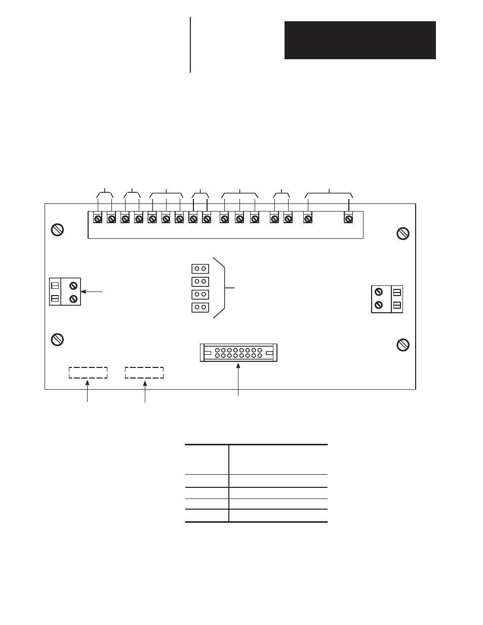
Feedback Board – The primary function of the board is to provide
scaling and transfer of feedback signals coming from power bridge devices
being sent to the Power Stage Interface and eventually to the Main Control
Board.
Figure 4.5
Feedback Board (A1) Overview
TB2
MFG Revision No.
Assembly Part No.
Connection for AC current
feedback burden resistor
(Factory Installed)
1
2
3
1
4
TB1
J2
TB3
ЛЛ
ЛЛ
5
6
7
8
9
11
13
15
17
18
20
23
J1
3
2
4
From DC
Current
Feedback
Sensor TD1
20 VAC
from
1 PT
AC Current
Feedback from
CTs ACT–1, 2 & 3
Field Current
Feedback from
FCT
3 Phase Incom-
ing AC Line
voltage Feed-
back
From Heatsink
Fan Switch
DC Armature Volt-
age Feedback
Connection to Power
Stage Interface
Jumper Selection
for Field Current
Feedback Scaling
(By User At Start-Up)
Note: No resister needed
on MKVA drives.
Table 4.A
Feedback Board Jumpers (see Table 8.J)
J1
Jumper
Position
125 – 300HP 240VDC
250 – 600HP 500VDC
Field Current Range
18.3– 42.4 ADC
8.6 – 18.4 ADC
2.3 – 8.7 ADC
1.0 – 2.4 ADC
1
2
3
4
- 20P PowerFlex DC Drive - Frame D Bimetal Thermostat (10 pages)
- 1336S_F_T_E_R F Frame Snubber Resistor Repl. (6 pages)
- 22-COMM PowerFlex 4-Class DSI (Drive Serial Interface) Network Communication Adapter (4 pages)
- 8-545 Plug In Solid State Relay (2 pages)
- 20-HIM-B1 PowerFlex 7-Class HIM Bezel (DPI) (4 pages)
- 100 Contactors with DC Coil (1 page)
- 100 Contactors with DC Coil (2 pages)
- 20P PowerFlex DC Drive - Frame D Switching Power Supply Circuit Board (6 pages)
- 140G-MTFx_MTHx_MTIx_MTKx Trip Unit Installation-140G-M (6 pages)
- 45BRD Analog Laser Sensor (4 pages)
- 20D Multi-Device Interface Option Board for PowerFlex 700S Drives (20 pages)
- 56RF RFID 18 mm Cylindrical Transceiver (2 pages)
- 42KC Miniature Rectangular: 5V DC Version (2 pages)
- 20P PowerFlex DC Drive - Frame A Switching Power Supply Circuit Board (16 pages)
- 21P-MISC-A-TP-2 Transition Tube Kit #C19-6/7 For PowerFlex 755 w/OEM Liquid Cooling Fr 6/7 Drive (2 pages)
- 42BT Background Suppression Sensor (3 pages)
- 42CB High Speed 18mm Cylindrical (4 pages)
- 140EX-JE2_JE3 Molded Case Circuit Breaker (4 pages)
- 140G-K-EAM1A Early Make Aux Contact for Rotary Handle Oper Mech-140G-K (1 page)
- 140G-K-EAM1A Early Make Aux Contact for Rotary Handle Oper Mech-140G-K (3 pages)
- 20-HIM-A6 PowerFlex (Human Interface Module) (74 pages)
- 42CF General Purpose 12mm Cylindrical (4 pages)
- 20D PowerFlex 700S Phase II Drive Frames 1...6 (80 pages)
- 140EX-HE1_HE2 Molded Case Circuit Breaker (6 pages)
- 140EX-HE1_HE2 Molded Case Circuit Breaker (4 pages)
- 20B PowerFlex 700 Custom Firmware - Pump Off (12 pages)
- 20-WIM-N4S DPI Wireless Interface Module (92 pages)
- 140U H-Frame Circuit Breaker Fixed and Adjustable Thermal Trip (7 pages)
- 140U H-Frame Circuit Breaker Fixed and Adjustable Thermal Trip (2 pages)
- 60-2619, 42JS Swivel/Tilt Mounting Bracket (1 page)
- 22A PowerFlex 4/40/400 Flange Mount (4 pages)
- 45MLA Controller Installation Instructions (16 pages)
- 20P PowerFlex DC Drive - Cooling Fan for Frame A Drives Above 73A at 230V 460V AC (6 pages)
- 42JS Series 7000 to 42JS VisiSight Replacement Kit (2 pages)
- 22A PowerFlex 4-Class HIM Bezel (DSI) (4 pages)
- 42CS Stainless Steel Photoelectric Sensors (4 pages)
- 20L-LL PowerFlex 700L Liquid-to-Liquid Heat Exchanger (40 pages)
- 20P PowerFlex DC Drive - Frame B SCR Modules (20 pages)
- 22B PowerFlex 40 Quick Start FRN 5.xx - 6.xx (161 pages)
- 22B PowerFlex 40 Quick Start FRN 5.xx - 6.xx (22 pages)
- 22F PowerFlex 4M Input RFI Filters (2 pages)
- 45LFM Capacitive Label Sensor (4 pages)
- 140G-Rx Installation Instruction-140G-R (29 pages)
- 140G-Rx Installation Instruction-140G-R (2 pages)
- 22C PowerFlex 400 AC Drive Quick Start - FRN 1-4.xx (28 pages)