Rockwell Automation 1395 Digital DC Drive FRN 5-10.10/9.30 User Manual
Page 157
Chapter 6
Installation
6-33
3. The analog input channel on the adapter board must now be scaled to
represent an accurate velocity feedback signal. First determine the
analog input signal for base speed. Parameter numbers are given in ( )
where applicable.
Base Motor Speed (606) x 9V
Max Speed
= Base Speed Input
4. The input voltage at base speed is then converted to Raw Adapter Units
according to the following equation.
Base Speed Input x 2048
10
= Raw Adapter Units
5. The Raw Adapter Units are then used to determine the correct scaling
parameter value according to the equation below.
4096
Raw Adapter Units
= Scaling Parameter Value
6. The Scaling Parameter Value should then be entered into the associated
analog input scaling set-up parameter. This procedure will be correct to
within 5%. Verify that the scaling is correct by measuring the actual
motor velocity with a hand tachometer. Fine tune the scaling by
adjusting the appropriate value to minimize any error.
7. Any drift at zero speed can be minimized by adjusting the offset
parameter associated with the channel in use.
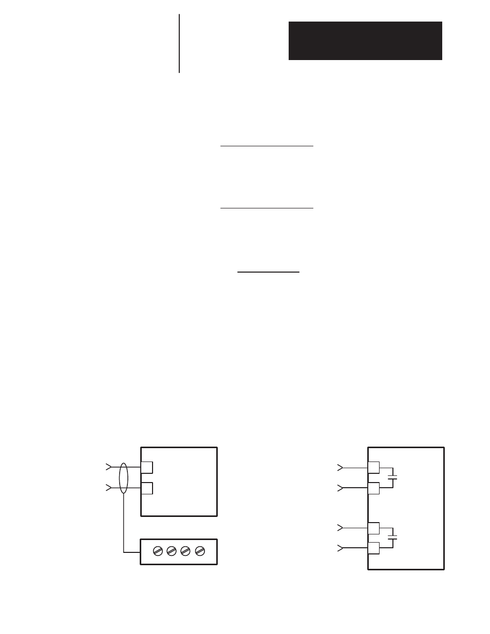
Analog Output – Figure 6.21 shows typical analog and digital output
connections.
Figure 6.21
Typical Output Connections
45
46
TB3
DIGITAL
Digital Output Connections
IMPORTANT: Connect
shield to drive end only.
Other end is to be insu-
lated and left floating.
34
38
TB3
ANALOG OUT +
ANALOG OUT COM.
Analog Output Connections
OUTPUT 1
DIGITAL
OUTPUT 2
44
43
Dry Contacts
0.6A at 125VAC,
2A at 30VDC
0 to
+
10VDC,
1mA Maximum
TB4 (TB-10 on 125-600 HP)