Rockwell Automation 1395 Digital DC Drive FRN 5-10.10/9.30 User Manual
Page 134
Chapter 6
Installation
6-10
As previously explained, two different types of grounds are used in the
1395 drive. They are defined as follows:
Ground (PE) - A Safety Ground is normally required by the electrical
code and is defined externally as PE ground. Main PE is located at the
ground stud next to the contactor. On MKVA: The PE ground stud is
located on the back panel between L2 & L3 ACT's and bus bars.
TB-X connections are for jumpering TE to PE for stand alone only. The
safety ground identified as PE ground is designated as follows:
· TB2 - 5
1-30 HP 230VAC
2-60 HP 460VAC
· TB2 - 7
40-100 HP 230VAC
75-200 HP 460VAC
· TB5 - 1 1
125-300 HP 230VAC
250-600 HP 460VAC
Depending on the specific application, PE ground as defined above may be
connected to a system ground bus when several drives are configured as
part of a system and mounted in the same cabinet. In other applications,
this terminal may be connected directly to a PE ground point consisting of
adjacent building steel (girder, joist, floor ground grid, etc.), provided
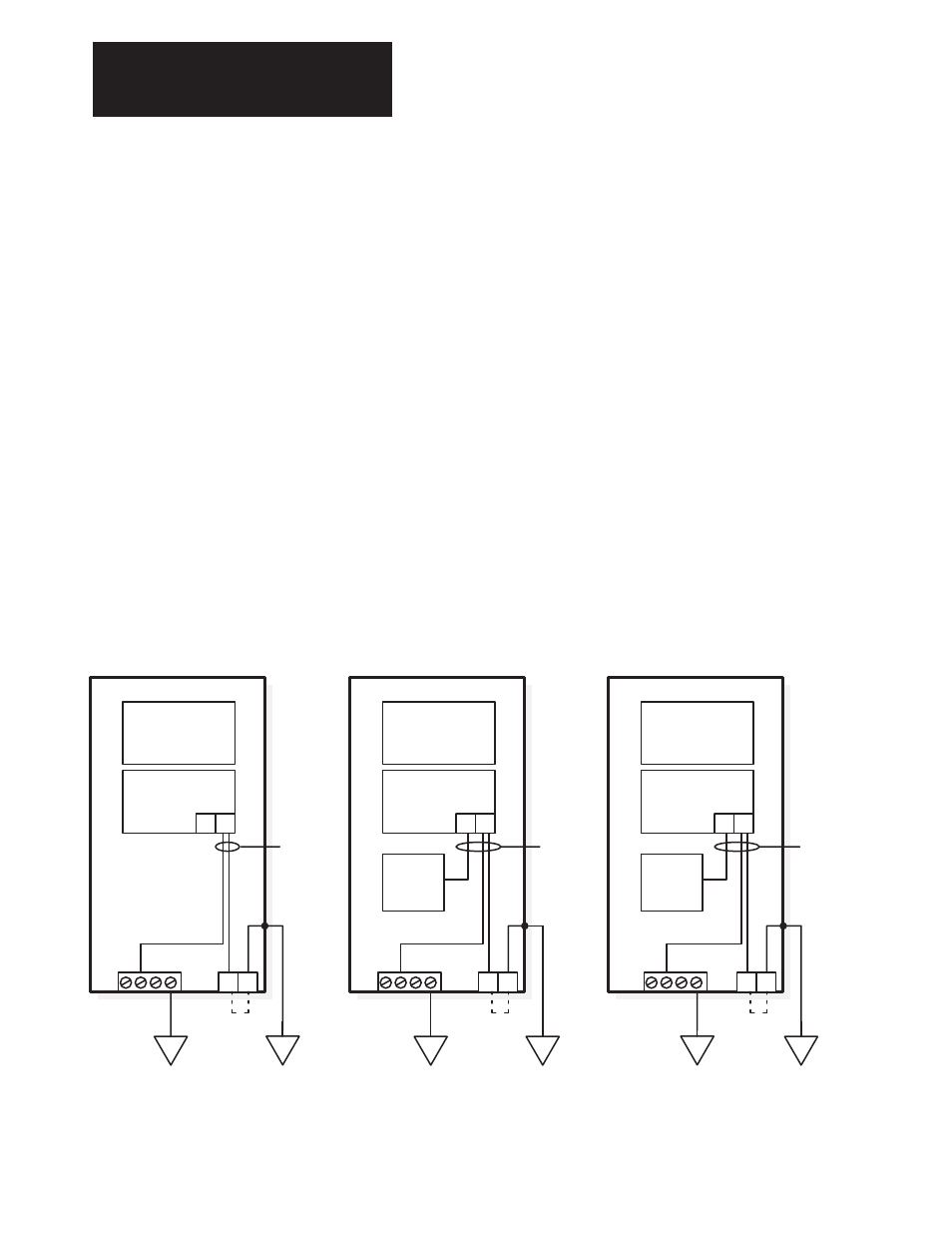
grounding points comply with NEC regulations. Figures 6.6 and 6.7
illustrate connection of PE for stand alone and system applications. PE
should be connected in a "Star" fashion, and not daisy chained.
Figure 6.6
Stand Alone Drive Grounding
6
7
Power Stage
Interface Board
Control
Boards
Unit
Power
Supply
TB2
TB4
GND
Control
(Signal)
Common
10 11
TB5
TB10
GND
Power Stage
Interface Board
Control
Boards
Unit
Power
Supply
Control
(Signal)
Common
40 - 100 HP 230V
125 - 300HP 230V
250 - 600HP 460V
1 - 30 HP 230V
2 - 60 HP 460V
125 - 300 HP 460V
TB2
TB4
GND
PSI/ Switcher
Board
Control
Boards
Control
(Signal)
Common
4
5
Signal
Wire
Shields
Signal
Wire
Shields
Signal
Wire
Shields
PE
TE
TE
PE
TE
PE
Zero Potential Bus (TE) - The Zero Potential Bus point is used for all
control signals internal to the drive. Depending on the application, TE may
be connected to a system TE bus or connected to PE ground. Figure 6.6
and 6.7 illustrate the possible connections for TE. If the drive is