Figure 7.12, 16 using multi-drive mode – Rockwell Automation 22-COMM-C ControlNet Adapter User Manual
Page 84
7-16
Using Multi-Drive Mode
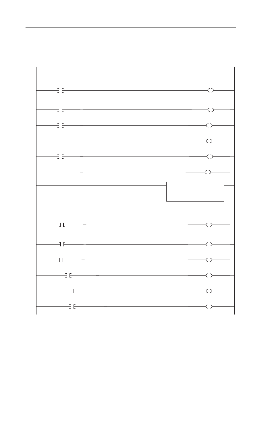
Figure 7.12 ControlLogix Drive 2 Control Subroutine
Drive 2 Control Subroutine
This section takes the data from the input image area and moves it to specific tags (Logic Status bits and Speed Feedback)
for use elsewhere in the ladder program.
0
Drive_Input_Image[4].0
Drive_2_Status_Ready
Drive 2 Control Subroutine
This section takes the data from the input image area and moves it to specific tags (Logic Status bits and Speed Feedback)
for use elsewhere in the ladder program.
1
Drive_Input_Image[4].1
Drive_2_Status_Active
2
Drive_Input_Image[4].3
Drive_2_Status_Forward
3
/
Drive_Input_Image[4].3
Drive_2_Status_Reverse
4
Drive_Input_Image[4].7
Drive_2_Status_Faulted
5
Drive_Input_Image[4].8
Drive_2_Status_At_Speed
6
Copy File
Source
Drive_Input_Image[5]
Dest Drive_2_Speed_Feedback
Length
1
COP
This section takes the data from specific tags (Logic Command bits and Speed Reference) and moves them to the output
image area for transmission to the scanner.
7
Drive_2_Command_Stop
Drive_Output_Image[4].0
This section takes the data from specific tags (Logic Command bits and Speed Reference) and moves them to the output
image area for transmission to the scanner.
8
Drive_2_Command_Start
Drive_Output_Image[4].1
9
Drive_2_Command_Jog
Drive_Output_Image[4].2
10
Drive_2_Command_Clear_Faults
Drive_Output_Image[4].3
11
Drive_2_Command_Forward_Reverse
Drive_Output_Image[4].4
12
/
Drive_2_Command_Forward_Reverse
Drive_Output_Image[4].5