Figure 4.7 – Rockwell Automation 22-COMM-C ControlNet Adapter User Manual
Page 39
Configuring the I/O
4-5
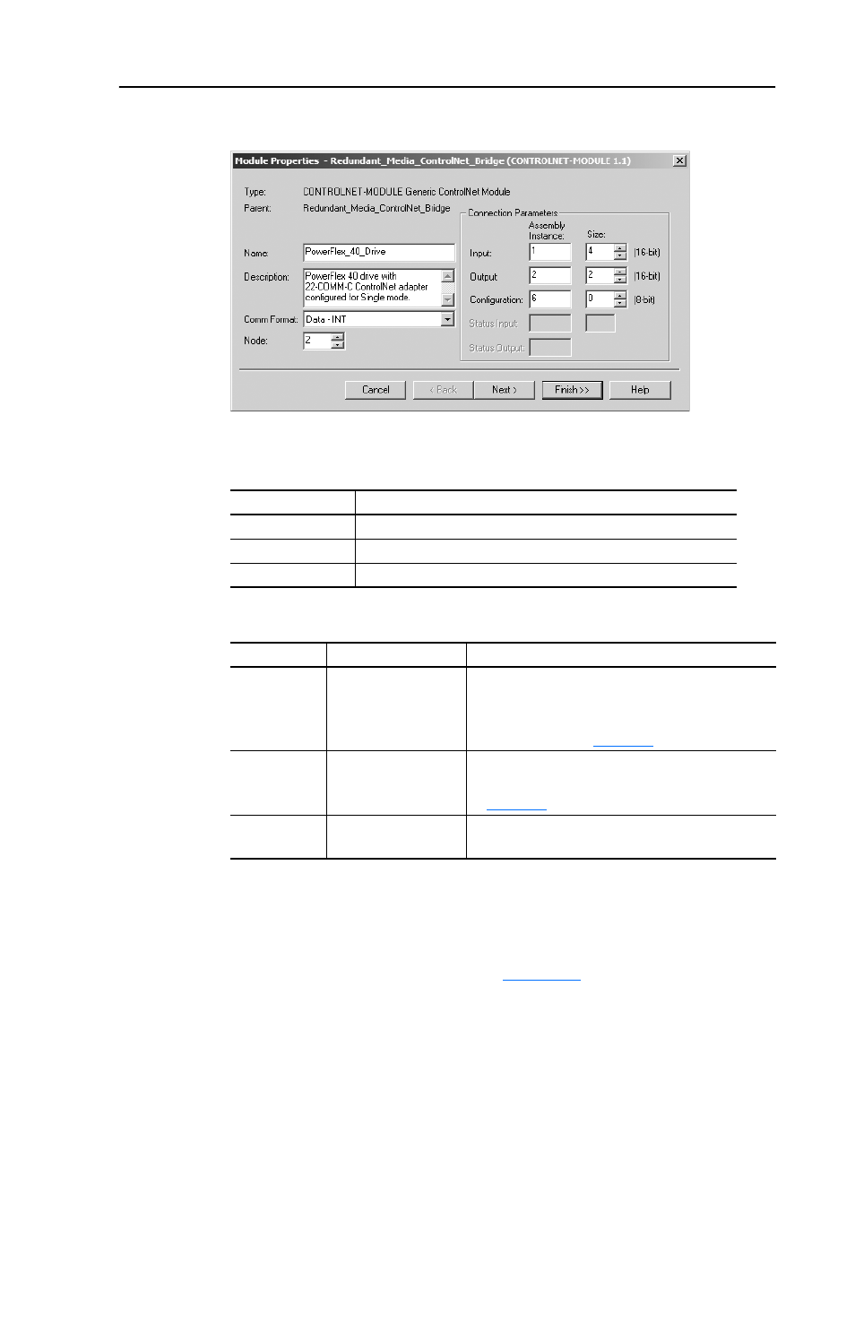
Figure 4.7 Module Properties Screen
3. Edit the following information about the adapter:
4. Under Connection Parameters, edit the following:
Enter the number of words that are required for your I/O in the Input
Size and Output Size boxes. The size will depend on the I/O that you
enabled in the adapter. This information can be found in Parameter
12 - [DSI I/O Cfg] in the adapter.
shows common
configuration Input/Output sizes.
In our example, we entered “4” in the Input Size and “2” in the
Output Size boxes because the Operating Mode Jumper on the
adapter is set to “1x” (Single mode, which is the default). Logic
Status/Feedback uses 2 words of input and an additional 2 words of
input are reserved for ControlNet bridge overhead. Logic Command/
Reference uses 2 words of output.
Box
Setting
Name
A name to identify the adapter and drive.
Comm Format
Data - INT (This setting formats the data in 16-bit words.)
Node
The node address setting of the adapter.
Box
Assembly Instance Size
Input
1 (This value is
required.)
The value will vary based on your application
(setting of Parameter 12 - [DSI I/O Cfg]). It will
contain 2 additional words for ControlNet bridge
overhead. Refer to
Output
2 (This value is
required.)
The value will vary based on your application
(setting of Parameter 12 - [DSI I/O Cfg]). Refer
to
.
Configuration 6 (This value is
required.)
0 (This value is required.)