Chapter 1, Getting started, Components – Rockwell Automation 22-COMM-C ControlNet Adapter User Manual
Page 13: Components -1, 1getting started, Chapter
Chapter
1
Getting Started
The 22-COMM-C ControlNet adapter is a communication option
intended for installation into a PowerFlex 40 or PowerFlex 400 drive. It
can also be used with other Allen-Bradley products that support a DSI
communication adapter, such as the DSI External Comms Kit
(22-XCOMM-DC-BASE). The External Comms Kit enables PowerFlex
4 drives (which cannot support an internally-mounted adapter) to
connect to a ControlNet network.
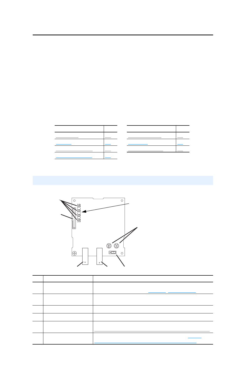
Figure 1.1 Components of the Adapter
Topic
Page
Topic
Page
Components
➋
➊
➌
➍
➎
➏
LEDs are located
on bottom side of
adapter board
Item Component
Description
➊
Status Indicators
Four LEDs that indicate the status of the ControlNet connection,
DSI, and the adapter. Refer to
➋
DSI Connector
A 20-pin, single-row shrouded male header. An Internal Interface
cable is connected to this connector and a connector on the drive.
➌
Channel A Coax Receptacle Channel A BNC connection for the ControlNet cable.
➍
Channel B Coax Receptacle Channel B BNC connection for the ControlNet cable.
➎
1x/5x Operating Mode
Jumper (J7)
Selects Single (1x) or Multi-Drive (5x) mode of operation. Refer to
Setting Operating Mode and Node Address Switches on page 2-1
.
➏
ControlNet Node Address
Switches
Sets a unique node address for the adapter. Refer to
Operating Mode and Node Address Switches on page 2-1
.