Figure 7.1 – Rockwell Automation 22-COMM-C ControlNet Adapter User Manual
Page 70
7-2
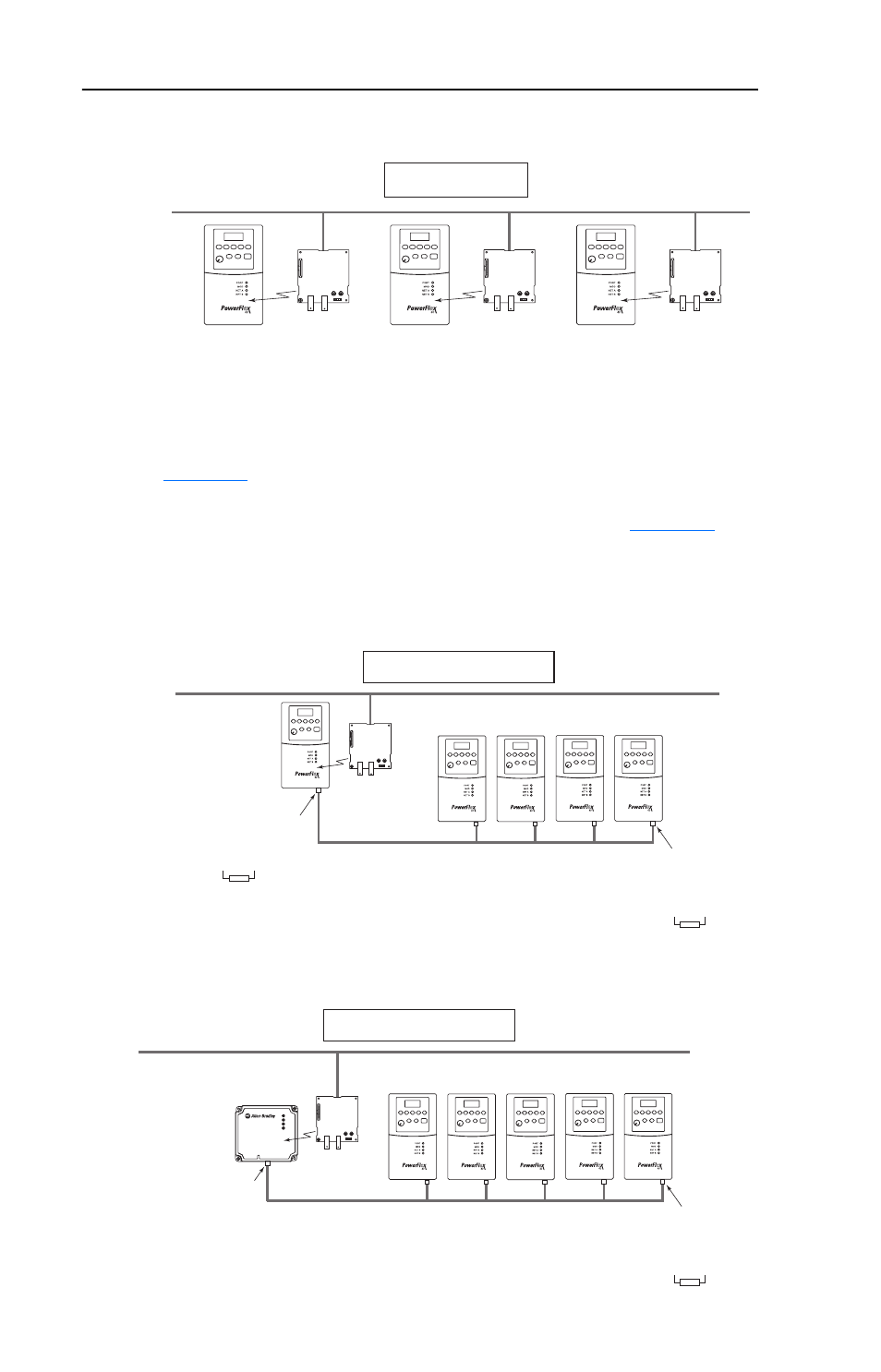
Using Multi-Drive Mode
Figure 7.1 Single Mode Example for Network
Multi-Drive mode is an alternative to the typical network installation,
where a single ControlNet node can consist of one to five drives. In
, the 22-COMM-C adapter is internally mounted in a
PowerFlex 40/400 drive, and the remaining PowerFlex 4-Class drives are
daisy-chained from the RS-485 port on the first drive. In
22-COMM-C adapter is externally mounted in a DSI External Comms
Kit, and all PowerFlex 4-Class drives are daisy-chained from it.
Figure 7.2 Multi-Drive Mode Example for Network - PowerFlex 40 Mounting
Figure 7.3 Multi-Drive Mode Example for Network - External Comms Kit Mounting
PowerFlex 40 or 400 Drive
with 22-COMM-C Adapter
PowerFlex 40 or 400 Drive
with 22-COMM-C Adapter
PowerFlex 40 or 400 Drive
with 22-COMM-C Adapter
ControlNet Network
1 drive per node
ControlNet Network
up to 5 drives per node
PowerFlex 40
or 400 Drive
22-COMM-C
Adapter
Up to 4 Additional PowerFlex 4-Class Drives
AK-U0-RJ45-TB2P
Connector with
Terminating Resistor
AK-U0-RJ45-TB2P
Connector with
Terminating Resistor
AK-U0-RJ45-TB2P
RS-485
ControlNet Network
up to 5 drives per node
DSI External Comms Kit
(22-XCOMM-DC-BASE)
22-COMM-C
Adapter
Up to 5 PowerFlex 4-Class Drives
NOTE: A terminating resistor
is not required for this end of
of the wiring. The resistor is
built into the circuitry of the
DSI External Comms Kit.
AK-U0-RJ45-TB2P
Connector with
Terminating Resistor
AK-U0-RJ45-TB2P
RS-485
PORT
MOD
NET A
NET B