10 using multi-drive mode – Rockwell Automation 22-COMM-C ControlNet Adapter User Manual
Page 78
7-10
Using Multi-Drive Mode
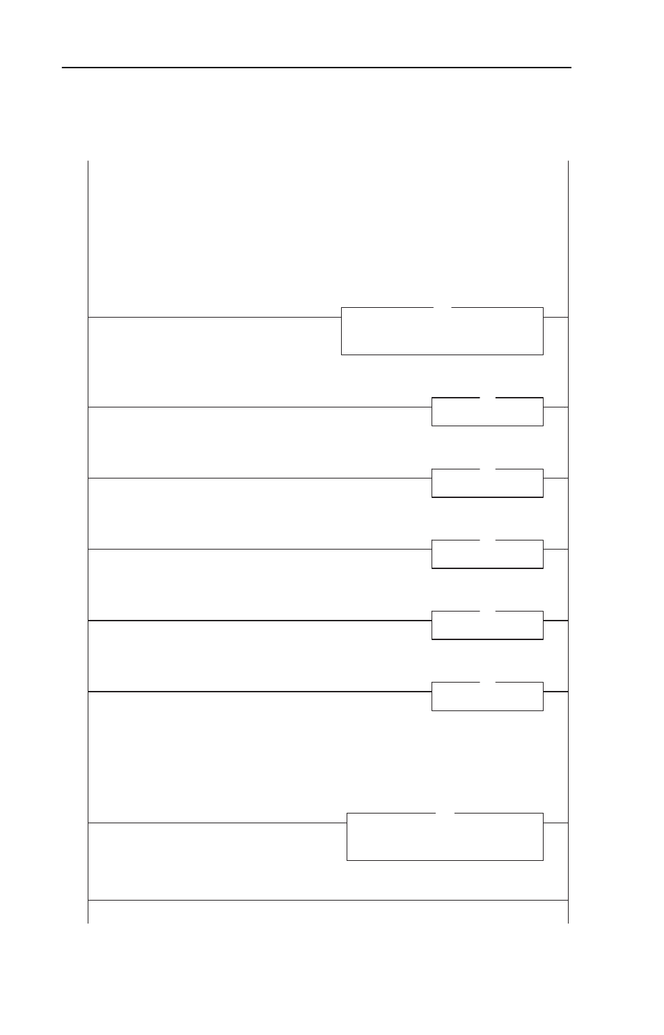
Figure 7.9 ControlLogix Main Routine
PowerFlex 40 ControlNet Multi-Drive Mode Example
ControlLogix Multi-Drive Mode example program with a PowerFlex 40 on ControlNet (22-COMM-C adapter). In this example,
Four (4) PowerFlex 4 drives are daisy-chained to the main PowerFlex 40 (with installed 22-COMM-C adapter) via their RJ-45
ports (RS-485). In this mode, a total of up to five (5) PowerFlex 4/40/400's can exist as one (1) ControlNet node on the
network.
This rung retrieves the Logic Status and Speed Feedback data for all five (5) drives from the scanner (array of INTs), and
moves them to specific INT tags for use elsewhere in the ladder program. The input image is as follows:
Drive_Input_Image[0] and Drive_Input_Image[1] = Drive 0 Logic Status and Speed Feedback
Drive_Input_Image[2] and Drive_Input_Image[3] = Drive 1 Logic Status and Speed Feedback
Drive_Input_Image[4] and Drive_Input_Image[5] = Drive 2 Logic Status and Speed Feedback
Drive_Input_Image[6] and Drive_Input_Image[7] = Drive 3 Logic Status and Speed Feedback
Drive_Input_Image[8] and Drive_Input_Image[9] = Drive 4 Logic Status and Speed Feedback
0
Copy File
Source _5_PowerFlex_4_Class_Drives:I.Data[2]
Dest
Drive_Input_Image[0]
Length
10
COP
PowerFlex 40 ControlNet Multi-Drive Mode Example
ControlLogix Multi-Drive Mode example program with a PowerFlex 40 on ControlNet (22-COMM-C adapter). In this example,
Four (4) PowerFlex 4 drives are daisy-chained to the main PowerFlex 40 (with installed 22-COMM-C adapter) via their RJ-45
ports (RS-485). In this mode, a total of up to five (5) PowerFlex 4/40/400's can exist as one (1) ControlNet node on the
network.
This rung retrieves the Logic Status and Speed Feedback data for all five (5) drives from the scanner (array of INTs), and
moves them to specific INT tags for use elsewhere in the ladder program. The input image is as follows:
Drive_Input_Image[0] and Drive_Input_Image[1] = Drive 0 Logic Status and Speed Feedback
Drive_Input_Image[2] and Drive_Input_Image[3] = Drive 1 Logic Status and Speed Feedback
Drive_Input_Image[4] and Drive_Input_Image[5] = Drive 2 Logic Status and Speed Feedback
Drive_Input_Image[6] and Drive_Input_Image[7] = Drive 3 Logic Status and Speed Feedback
Drive_Input_Image[8] and Drive_Input_Image[9] = Drive 4 Logic Status and Speed Feedback
Drive 0 control subroutine.
1
Jump To Subroutine
Routine Name
Drive_0
JSR
Drive 0 control subroutine.
Drive 1 control subroutine.
2
Jump To Subroutine
Routine Name
Drive_1
JSR
Drive 1 control subroutine.
Drive 2 control subroutine.
3
Jump To Subroutine
Routine Name
Drive_2
JSR
Drive 2 control subroutine.
Drive 3 control subroutine.
4
Jump To Subroutine
Routine Name
Drive_3
JSR
Drive 3 control subroutine.
Drive 4 control subroutine.
5
Jump To Subroutine
Routine Name
Drive_4
JSR
Drive 4 control subroutine.
This rung writes the output image to the scanner. The output image is as follows:
Drive_Output_Image[0] and Drive_Output_Image[1] = Drive 0 Logic Command and Speed Reference
Drive_Output_Image[2] and Drive_Output_Image[3] = Drive 1 Logic Command and Speed Reference
Drive_Output_Image[4] and Drive_Output_Image[5] = Drive 2 Logic Command and Speed Reference
Drive_Output_Image[6] and Drive_Output_Image[7] = Drive 3 Logic Command and Speed Reference
Drive_Output_Image[8] and Drive_Output_Image[9] = Drive 4 Logic Command and Speed Reference
(Note the length of the COP instruction is "10" because the Destination address is an INT)
6
Copy File
Source
Drive_Output_Image[0]
Dest _5_PowerFlex_4_Class_Drives:O.Data[0]
Length
10
COP
This rung writes the output image to the scanner. The output image is as follows:
Drive_Output_Image[0] and Drive_Output_Image[1] = Drive 0 Logic Command and Speed Reference
Drive_Output_Image[2] and Drive_Output_Image[3] = Drive 1 Logic Command and Speed Reference
Drive_Output_Image[4] and Drive_Output_Image[5] = Drive 2 Logic Command and Speed Reference
Drive_Output_Image[6] and Drive_Output_Image[7] = Drive 3 Logic Command and Speed Reference
Drive_Output_Image[8] and Drive_Output_Image[9] = Drive 4 Logic Command and Speed Reference
(Note the length of the COP instruction is "10" because the Destination address is an INT)
(End)