6 using the i/o – Rockwell Automation 22-COMM-C ControlNet Adapter User Manual
Page 56
5-6
Using the I/O
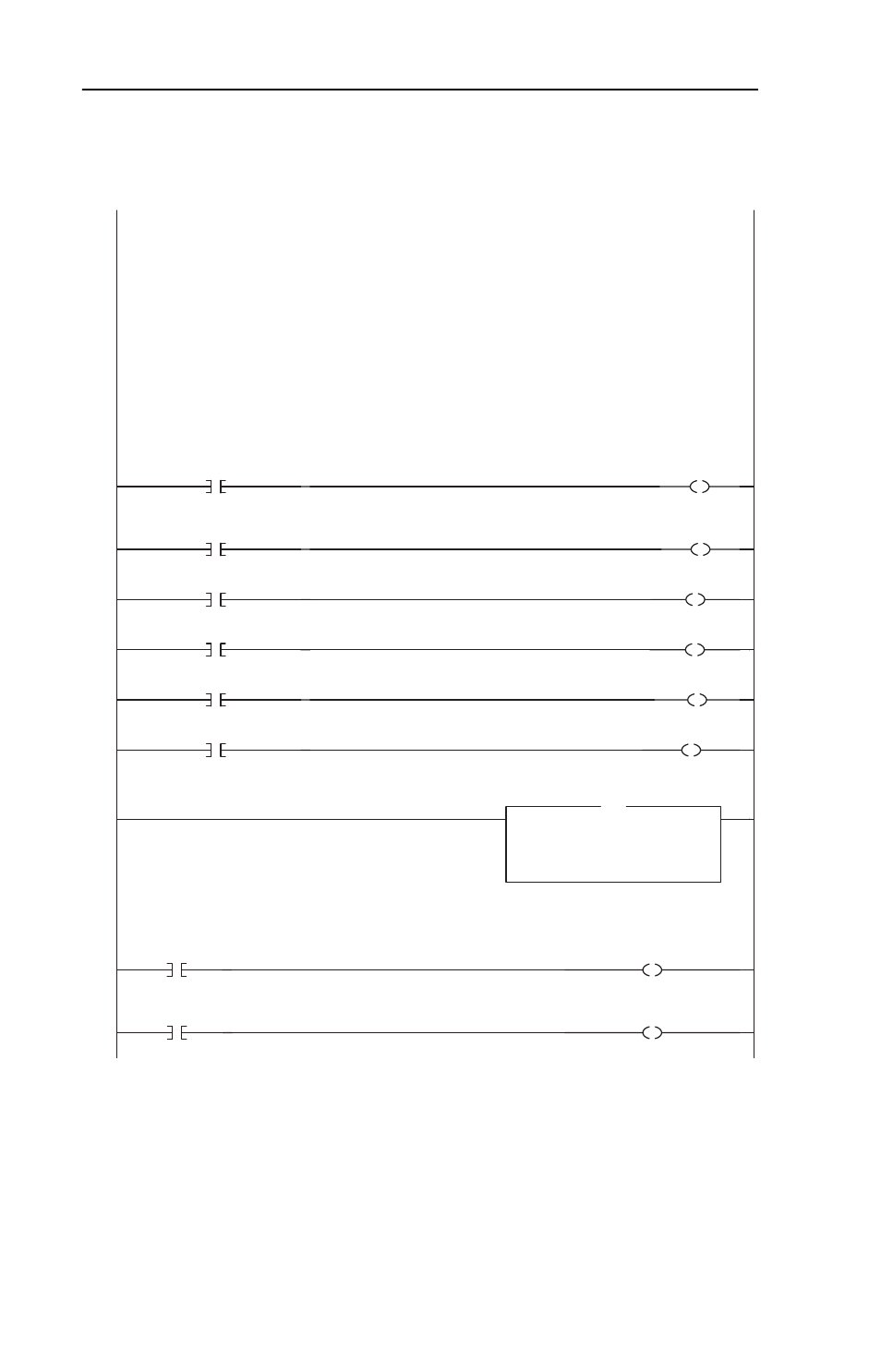
Figure 5.3 ControlLogix Ladder Logic Example for Drive I/O Control
PowerFlex 40 ControlNet Single Mode Example
This ControlLogix example system consists of a 1756-CNBR/D in Slot 4 communicating on a ControlNet network with a
PowerFlex 40 drive with an installed 22-COMM-C ControlNet adapter. You may substitute the "PowerFlex 40" for a
PowerFlex 400, or a PowerFlex 4 using an External DSI Communicaitons Kit (22-XCOMM-DC-BASE).
The I/O image is as follows:
INPUT (4 INT words)
PowerFlex_40_Drive:I.Data[0] = 1756-CNBR Overhead (Not Used)
PowerFlex_40_Drive:I.Data[1] = 1756-CNBR Overhead (Not Used)
PowerFlex_40_Drive:I.Data[2] = PowerFlex 40 Logic Status
PowerFlex_40_Drive:I.Data[3] = PowerFlex 40 Speed Feedback
OUTPUT (2 INT words)
PowerFlex_40_Drive:O.Data[0] = PowerFlex 40 Logic Command
PowerFlex_40_Drive:O.Data[1] = PowerFlex 40 Speed Reference
Logic Status information rungs are provided for display purposes only. The PowerFlex_40_Drive:I.Data[2].x bits could be
used directly elsewhere in the ladder program.
0
PowerFlex_40_Drive:I.Data[2].0
Status_Ready
PowerFlex 40 ControlNet Single Mode Example
This ControlLogix example system consists of a 1756-CNBR/D in Slot 4 communicating on a ControlNet network with a
PowerFlex 40 drive with an installed 22-COMM-C ControlNet adapter. You may substitute the "PowerFlex 40" for a
PowerFlex 400, or a PowerFlex 4 using an External DSI Communicaitons Kit (22-XCOMM-DC-BASE).
The I/O image is as follows:
INPUT (4 INT words)
PowerFlex_40_Drive:I.Data[0] = 1756-CNBR Overhead (Not Used)
PowerFlex_40_Drive:I.Data[1] = 1756-CNBR Overhead (Not Used)
PowerFlex_40_Drive:I.Data[2] = PowerFlex 40 Logic Status
PowerFlex_40_Drive:I.Data[3] = PowerFlex 40 Speed Feedback
OUTPUT (2 INT words)
PowerFlex_40_Drive:O.Data[0] = PowerFlex 40 Logic Command
PowerFlex_40_Drive:O.Data[1] = PowerFlex 40 Speed Reference
Logic Status information rungs are provided for display purposes only. The PowerFlex_40_Drive:I.Data[2].x bits could be
used directly elsewhere in the ladder program.
1
PowerFlex_40_Drive:I.Data[2].1
Status_Active
2
PowerFlex_40_Drive:I.Data[2].3
Status_Forward
3
/
PowerFlex_40_Drive:I.Data[2].3
Status_Reverse
4
PowerFlex_40_Drive:I.Data[2].7
Status_Faulted
5
PowerFlex_40_Drive:I.Data[2].8
Status_At_Speed
This rung displays the Speed Feedback word from the PowerFlex 40. Note that it is set in Hz and not in engineering units
like PowerFlex 7-Class drives. For example, "300" equates to 30.0 Hz (the decimal point is always implied).
6
Move
Source PowerFlex_40_Drive:I.Data[3]
0
Dest
Speed_Feedback
0
MOV
This rung displays the Speed Feedback word from the PowerFlex 40. Note that it is set in Hz and not in engineering units
like PowerFlex 7-Class drives. For example, "300" equates to 30.0 Hz (the decimal point is always implied).
Logic Command bit control rungs are provided for display purposes only. The PowerFlex_40_Drive:O.Data[0].x bits could be
used directly elsewhere in the ladder program.
7
Command_Stop
PowerFlex_40_Drive:O.Data[0].0
Logic Command bit control rungs are provided for display purposes only. The PowerFlex_40_Drive:O.Data[0].x bits could be
used directly elsewhere in the ladder program.
8
Command_Start
PowerFlex_40_Drive:O.Data[0].1